Reconstructing the Cooling Tower
A natural-draft cooling tower is easy to recognize from a distance. Understanding it is something else. This article follows the reconstruction of a cooling tower beyond its familiar silhouette, toward the internal logic of water distribution, airflow, evaporation, access, and heat rejection.
• June 3, 2026
Beyond the Familiar Silhouette
A natural-draft cooling tower is easy to recognize from a distance.
Its silhouette is familiar long before its function is understood. It stands at the edge of a power plant like a landmark, often larger in public imagination than the system it actually belongs to. For many people, the cooling tower has become a visual shorthand for nuclear energy itself.
But a cooling tower is not the reactor. It is not where fission takes place, where nuclear heat is generated, where control rods move, or where the primary safety logic of the reactor core is located. Its role belongs to another part of the plant.
A natural-draft cooling tower is part of the heat-rejection system. It is connected to the part of the power cycle where heat that cannot be converted into useful electrical work must leave the system. After steam has delivered energy through the turbine, it must be condensed back into water. That condensation requires cooling. The cooling tower supports that process by allowing large volumes of warm circulating water to reject heat to the atmosphere.
From a distance, this may look simple: a large shell, a visible plume, and a familiar industrial profile. From close up, the object becomes something else. It becomes a structure of access, inspection, geometry, surface, water distribution, airflow, maintenance routes, and operational purpose.
The silhouette is familiar. The internal logic is where the real work begins.
Removing the Symbol from the Object
Before modelling any part of the cooling tower, I first had to study the structure beyond its public image.
That step matters.
In technical visualization, there is always a risk of modelling the object as it is commonly recognized, instead of modelling it as it actually works. With cooling towers, that risk is especially strong because the outer form is so dominant. The hyperbolic shell is visually powerful, memorable, and almost architectural in the way it occupies space.
But the shell alone does not explain the system.
A cooling tower is not defined only by its outer curve. It is defined by the coordination of internal processes: hot water is brought upward, distributed across a large plan area, broken into droplets, spread over fill material, contacted by rising air, partially cooled through evaporation, and collected again in a basin.
That is the difference between drawing a landmark and reconstructing a system. A landmark is recognized. A system has to be read.
Water, Air, Evaporation, Recovery
The basic logic of a natural-draft cooling tower is direct, but not trivial.
Hot water is transported upward through risers and then distributed through flumes and lateral piping. Nozzles discharge the water into droplet form, allowing it to fall through the internal fill system.
The fill is not incidental. Its purpose is to increase the contact area and residence time between falling water and rising air. This is where much of the cooling duty is achieved. The tower is not merely a hollow concrete volume with water falling through it. It is a carefully arranged heat and mass transfer environment.
Drift eliminators reduce the amount of water droplets carried out with the rising air. They help the tower separate heat rejection from unnecessary water loss, allowing humid air to leave while limiting the escape of liquid water.
Air enters at the base of the tower. As the air inside the tower is heated and humidified, it becomes less dense and rises. This creates the natural draft effect. The tower therefore should not be read only as a shell, but as a vertical flow path. Air is drawn in, moves through the rain zone and fill region, passes through drift control, and exits through the top as warm humid air.
Part of the water evaporates during this process, and that evaporation is central to the cooling function. The visible plume associated with cooling towers is not smoke from combustion and it is not a sign of nuclear release. It is mainly the visible result of warm, humid air leaving the tower and mixing with cooler ambient air.
This distinction is not cosmetic. It changes how the structure should be understood.
The plume is not a symbol of danger. It is part of the thermodynamic boundary between the plant and the atmosphere.
The Shell Is Not Decoration
The hyperbolic form of a natural-draft cooling tower is often treated as an aesthetic object because it is so visually distinctive. But in engineering terms, the shape is not decorative.
The shell has to support airflow, height, structural stability, crosswind resistance, and material efficiency. It creates the vertical body through which the natural draft process can occur, while also carrying its own structural demands as a very large reinforced concrete form.
This is where the visual reconstruction becomes more demanding.
If the tower is modelled only as a smooth outer skin, it may be recognizable, but it remains incomplete. The shell has to connect to the lower support structure. The air inlet zone has to make sense. Access platforms, ladders, walkways, railings, service structures, surface details, openings, and inspection routes must not feel randomly attached. They have to belong to the logic of the object.
The closer one gets, the less the tower behaves like an icon. It becomes infrastructure. It becomes work.
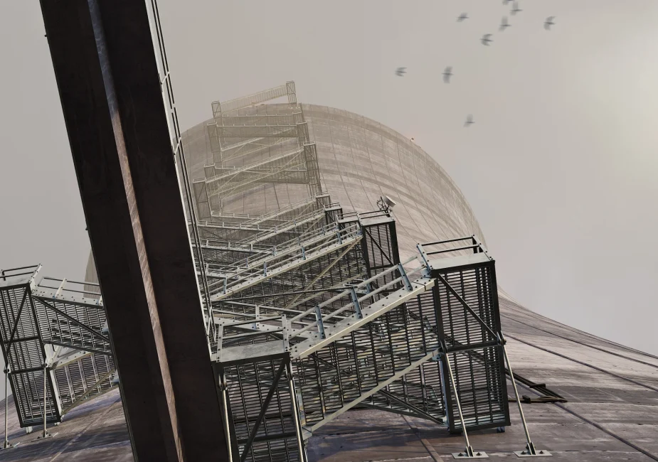
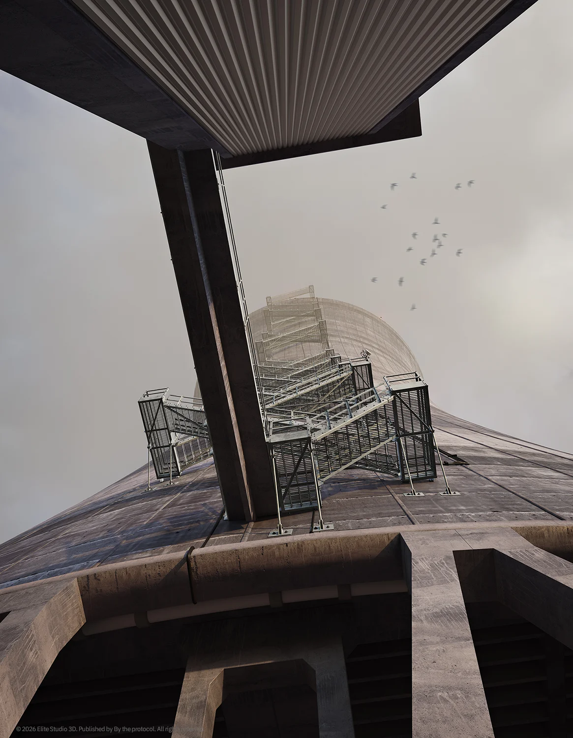
Test Renders as Verification
The test renders included here belong to the verification stage of the reconstruction process.
At this point, the purpose was not atmosphere, final lighting, material treatment, or visual polish. The purpose was to check whether the structure could begin to read correctly. Scale, access routes, platform logic, structural hierarchy, and operational credibility had to be tested before the final image could carry any real weight.
That is why a test render is not merely an unfinished image.
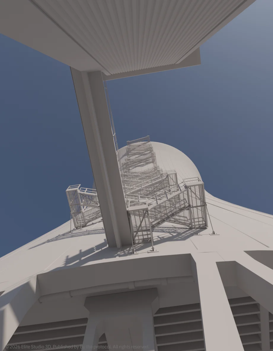
In documentation-driven reconstruction, a test render is part of the thinking process. It shows the moment before the image becomes visually complete, when the structure is still being questioned.
This stage matters because technical visualization cannot rely only on final atmosphere. A strong render can hide weak logic for a moment, but it cannot replace structural understanding. The model has to survive closer inspection before it can carry a final image with confidence.
The test render is where the object is still being interrogated. The final render is where that interrogation becomes visible as form.
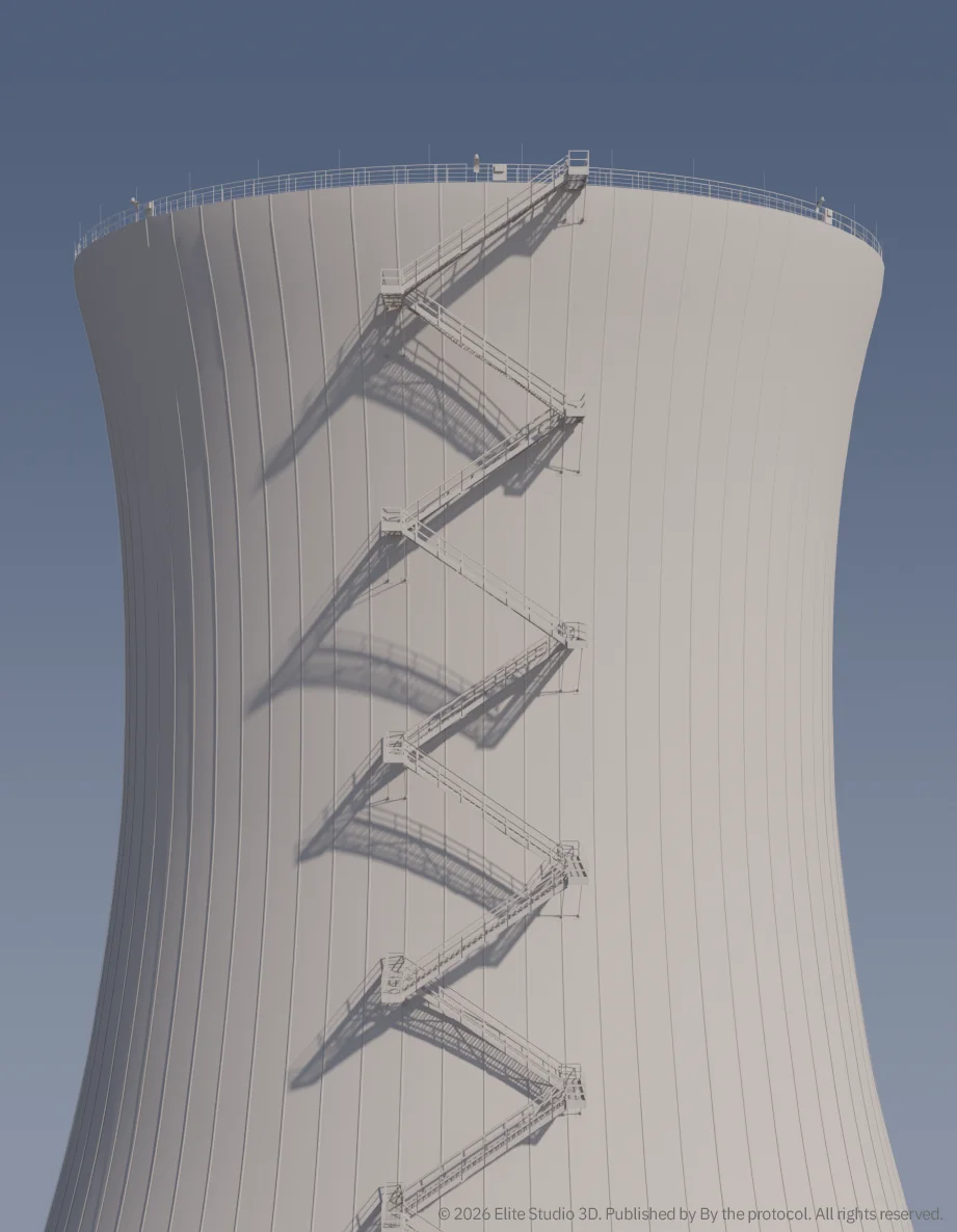
Final Render as Technical Reading
The final render builds on the earlier verification stage.
It adds atmosphere, material depth, surface reading, lighting, and scale. But those elements are not the foundation. They are the final layer. The image only works if the underlying structure already carries the logic of the system.
This is the part of reconstruction that interests me most: not the moment when the object becomes beautiful, but the moment when it becomes believable.
A cooling tower can easily become dramatic in an image. Its height, curve, weather, surface staining, visible plume, and industrial setting almost invite drama. But drama is not the goal here.
The goal is technical reading.
The viewer should feel that the structure has weight, that it has access routes, that it can be inspected, and that water, air, maintenance, and geometry all belong to the same object. The tower should not read as a backdrop, but as a functional volume.
The final image is therefore not only an exterior visualization. It is a reading of the tower as a heat-rejection structure.
Where Heat Leaves the System
A power plant is often explained from the source of heat outward.
In a nuclear plant, attention naturally begins with the reactor. The reactor core, fuel, control rods, coolant, pressure boundary, and safety systems carry the strongest conceptual weight. That is understandable, because they are central to the plant’s identity and safety logic.
But the power cycle does not end at the reactor.
It continues through steam generation, turbine expansion, condensation, cooling, and heat rejection. The cooling tower belongs to this final part of the energy conversion chain. It is where unused heat leaves the system and returns to the environment through controlled thermal exchange.
The cooling tower is outside the reactor system and outside the primary nuclear process, but it is not outside the logic of the plant. It belongs to the broader thermal cycle, where heat that remains after energy conversion in the steam and turbine system is finally rejected to the environment. In that sense, the cooling tower is not the place where nuclear heat is produced, but it is part of the plant’s ability to complete the heat balance.
This dual position is exactly why it deserves careful reconstruction. Not because it is mysterious, but because it is too often reduced to a symbol.
From Landmark to System
Reconstructing a cooling tower means moving beyond recognition.
The familiar silhouette is only the beginning. It tells us what the object is called, but not what it does. To understand the tower, one has to move closer: into the lower air inlet, through the support structure, toward the water distribution level, across platforms, along access routes, and into the coordination between water, air, evaporation, drift control, and recovery.
That is where the tower stops being a shape and becomes a system.
A natural-draft cooling tower is not the reactor, not a source of nuclear heat, and not a dramatic symbol of danger. It is a large, disciplined, thermodynamic structure whose purpose is to reject heat. Its form carries airflow, its internal arrangement carries water, and its details carry access, inspection, and maintenance.
From far away, it is a landmark. From close up, it is a structure that has to work. And that is where reconstruction begins.
Note
This reconstruction is an independent technical interpretation of a natural-draft cooling tower, based on publicly available documentation, technical references and visual study.
It is not an official model of any specific power plant, cooling tower vendor, utility, engineering contractor or proprietary system. It does not represent vendor-issued drawings, as-built documentation, licensed plant data or confidential engineering information.
The reconstruction was created for educational, technical communication and analytical purposes only. It is not intended for design, construction, engineering verification, operation, safety analysis, regulatory review or licensing use.
All visual material, 3D reconstruction work, renders, diagrams, written analysis and related explanatory content remain the intellectual property of Elite Studio 3D / By the Protocol unless stated otherwise.
Reference
John W. Cooper, Jr., P.E., Introduction to Natural Draft Cooling Towers for Electric Power Generating Plants, SunCam online continuing education course, 2018.
3D Reconstruction Balance of Plant By the Protocol Cooling Tower Cooling Water Documentation-Driven Reconstruction Drift Eliminators Engineering Visualization Evaporation Heat Rejection Industrial Infrastructure Natural Draft Natural Draft Cooling Tower Nuclear Communication Power Plant Systems technical reconstruction Thermal Systems
Last modified: June 3, 2026