Reconstructing an SMR RPV from the Inside Out
A documentation-driven reconstruction of a NuScale-style SMR reactor pressure vessel, developed from internal volume and system topology toward upper internals, CRA and ICI penetrations, CRDM housing interfaces, feedwater geometry, and containment vessel constraints.
• May 28, 2026
How compact reactor geometry concentrates interfaces, constraints, and reconstruction discipline
Small modular reactors are often described through their size. Smaller footprint. Modular fabrication. Integrated systems. Compact architecture. But in this context, small does not mean technically simple. It refers primarily to modular scale and power output, not to physical triviality or reduced engineering complexity. In technical reconstruction, compactness does not simplify the system. It increases the density of relationships that must be interpreted correctly.
It compresses relationships that would be more spatially separated in a conventional PWR. Primary flow paths, internal structures, heat transfer surfaces, feedwater and steam generator interfaces, penetrations, support logic, control rod interfaces, instrumentation routes, and containment constraints are brought into much closer physical proximity.
This has been one of the central lessons of my SMR reactor pressure vessel reconstruction work. The challenge was never only to model individual components. The challenge was to understand how they relate to each other inside a compact nuclear system.
Starting with the vessel, not the details
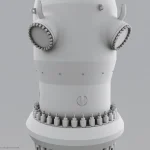
A reconstruction of this type cannot begin with surface detail. It has to begin with the system body. The first step was to establish the reactor pressure vessel as a spatial and functional volume: its proportions, topology, internal hierarchy, and the logic of what must fit inside it. Only after that could the dependent systems begin to make sense.
Complex systems are built in layers. The RPV comes first: volume, topology, internal logic.
Penetrations, feedwater and steam plenum geometry, CRA and ICI connections, upper assembly interfaces, and CRDM geometry follow from that logic. They cannot be placed independently without creating cumulative error later in the reconstruction.
This sequence matters because in an integral SMR, geometry is not simply a container for the system. Geometry becomes part of the system.
From system clarity to system embodiment
Compared with an integral SMR, a conventional PWR can be more didactic to interpret spatially. The major systems are more visibly separated. The primary loop, secondary loop, safety systems, steam generators, pumps, piping runs, and containment volumes can be understood as distinct systems with clearer spatial boundaries.
That separation supports explanation. It also supports reconstruction. An integrated SMR changes that logic. In a NuScale-type integral PWR configuration, major functions are arranged within a much tighter physical architecture. Primary flow, heat removal, passive safety features, internal structures, steam generator geometry, pressure boundary constraints, and containment relationships coexist within a compact module.
System boundaries are no longer always visually obvious. They are physical, functional, and interface-driven.
This means the reconstruction approach changes. Instead of assembling a sequence of separated components, the work becomes a study of mass distribution, internal envelopes, flow paths, plena, penetrations, access logic, and structural constraints inside one compact body.
You no longer model a machine. You model a system body.
Compactness does not remove complexity
The visual impression of an SMR can be misleading. In a render, the system may appear compact, controlled, almost simple. But compactness can hide the density of the engineering problem. Every curvature, penetration, opening, support, cover, plenum, nozzle, and interface carries consequences. A small shift in one region can affect alignment, access, clearances, or the plausibility of adjacent systems.
This is especially important when working from public documentation. The reconstruction is not a free interpretation. It has to remain disciplined. Where geometry is supported by publicly available documentation, it can be modelled with confidence. Where it is unclear, it must be simplified, left unresolved, or omitted.
That decision is not a weakness. It is part of the reconstruction discipline. Credibility in nuclear system visualization does not come from adding visual detail everywhere. It comes from knowing where detail is justified, and where restraint is more accurate.
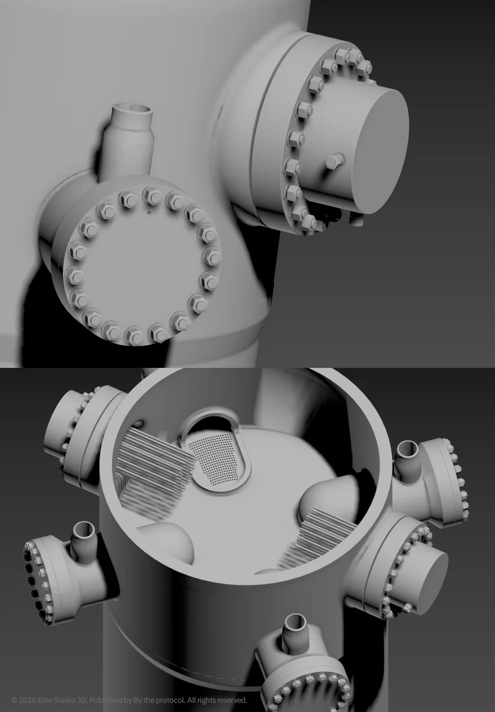
Feedwater and steam plenum geometry as system logic
One of the important areas in the reconstruction was the feedwater and steam plenum region. In an integral PWR/SMR configuration, feedwater geometry is not an isolated detail. It is connected to secondary-side flow stability, heat transfer paths, inspection access, and the spatial logic of the steam generator system.
But the feedwater side is only one part of the interface. The steam plenum region is equally important because it represents the outlet side of the steam generator architecture inside the integrated RPV. It connects the steam generator tube region, steam collection and routing logic, access geometry, main steam outlet relationship, and surrounding upper vessel structure.
For reconstruction, this made the plenum region more than a set of openings or covers. It became a key interface zone. The model therefore had to treat the feedwater plenum access port, flow restrictor mounting logic, removable cover arrangement, feedwater supply nozzle relationship, tubesheet integration, integral steam plenum, steam plenum access ports, and main steam outlet relationship as functional geometry.
This was not about making the cutaway visually interesting. It was about making the system readable. A feedwater feature is meaningful because it helps explain how secondary-side water is introduced, shaped, restricted, distributed, and guided into the heat transfer region.
A steam plenum feature is meaningful because it helps explain how steam leaves that region, how access is provided, and how the outlet side of the steam generator system is integrated into the upper RPV architecture. In compact reactor architecture, both sides belong to the same larger thermal-hydraulic picture. Small details become system clues.
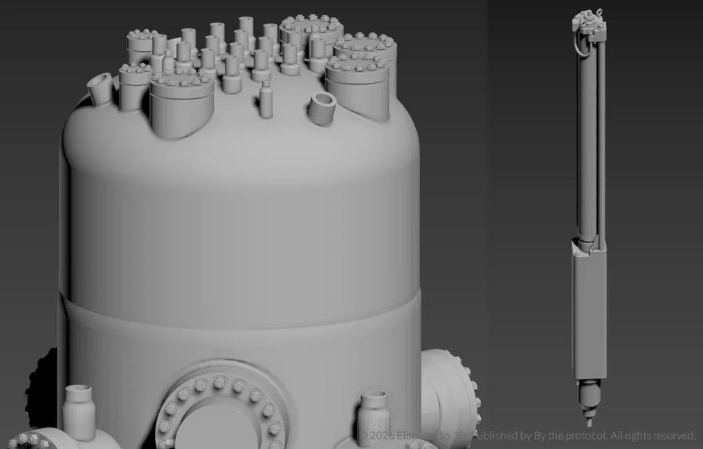
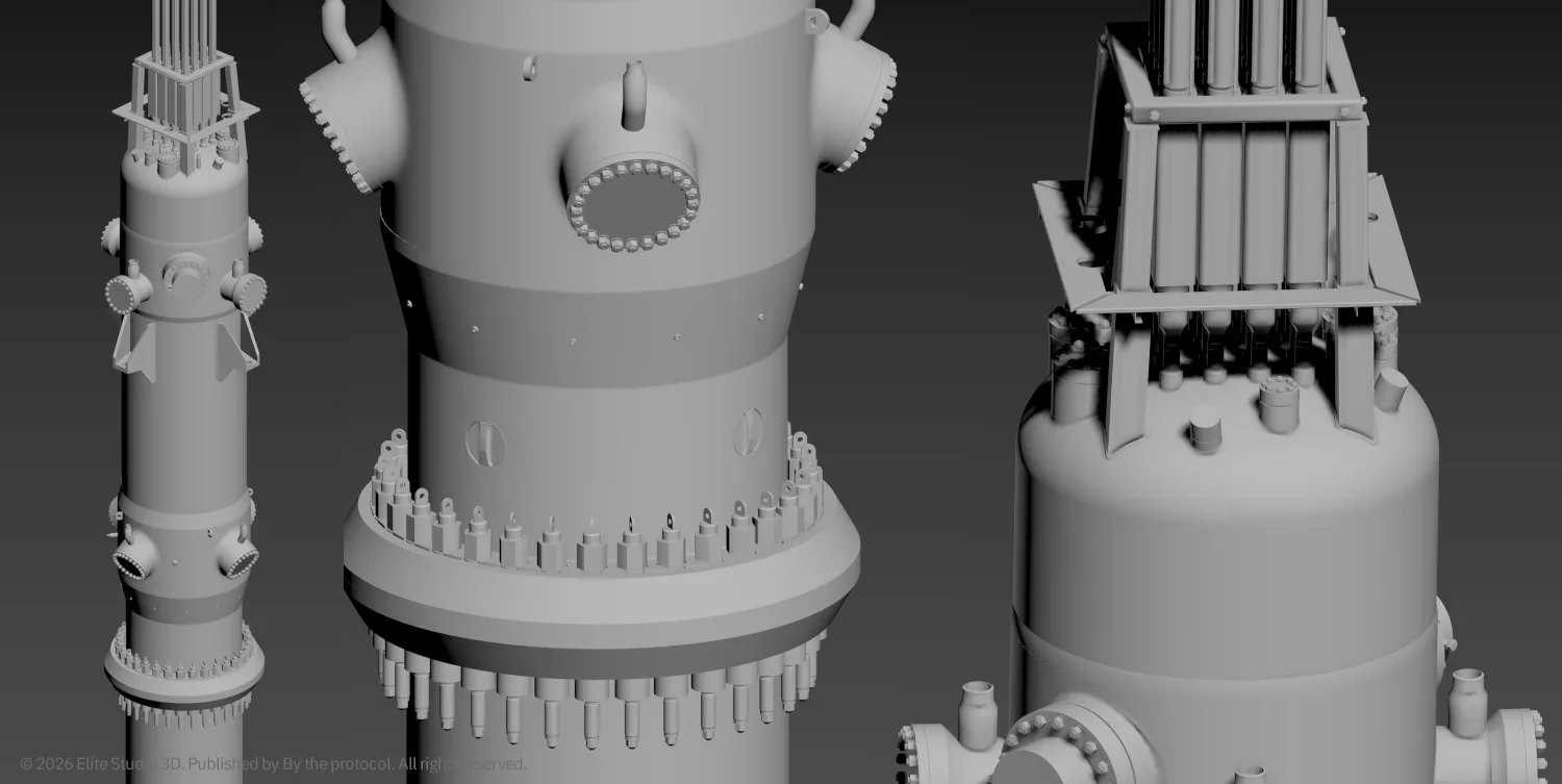
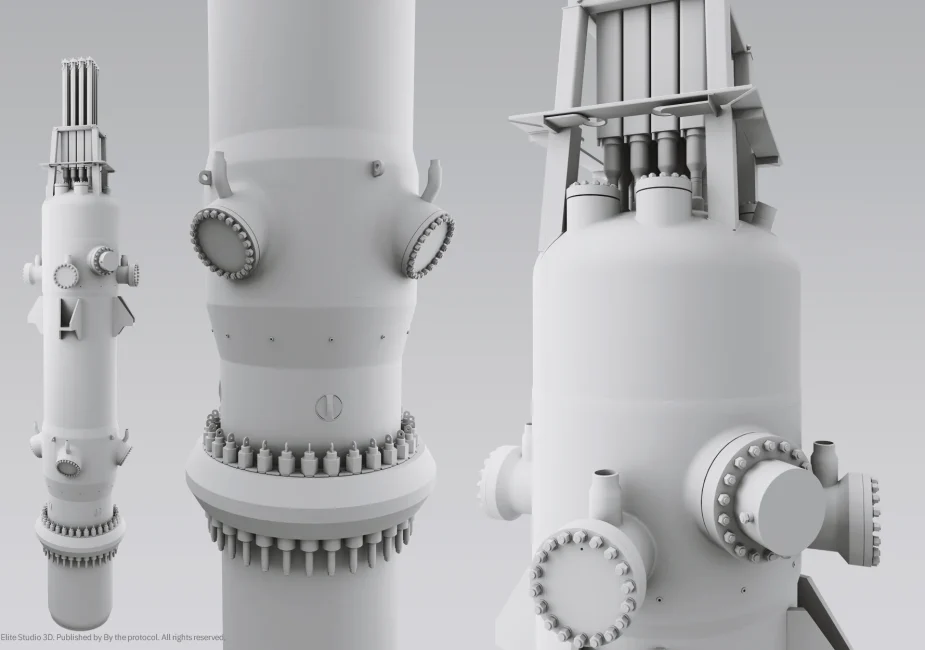
The upper RPV as a crowded interface region
The upper section of the RPV became one of the most demanding areas of the reconstruction. It is tempting to read the upper vessel as a simple vertical sequence: steam generator region, steam plenum, pressurizer region, top head, CRDM area. In practice, these areas are tightly related.
The steam generator tubes, feedwater plena, steam plena, main steam nozzles, feedwater nozzles, pressurizer boundary, access covers, CRDM penetrations, support features, and containment vessel constraints all occupy a limited spatial envelope. This creates a reconstruction problem that is not solved by modelling each feature separately.
It has to be solved by understanding hierarchy. Which geometry defines the envelope Which interfaces must align? Which access features must remain plausible? Which components belong to the pressure boundary? Which features can be shown from public documentation, and which should remain simplified?
In this region, compactness becomes very visible. The upper RPV is not just the top of the reactor vessel.
It is a dense transition zone between heat transfer, steam generation, pressure control, control rod drive geometry, inspection access, and containment constraints.
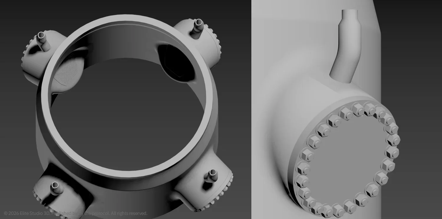
The CRDM region as an interface zone
The control rod drive mechanism region became another demanding part of the reconstruction. At first glance, CRDM housings may appear to be upper-vessel details. In practice, they are interface assemblies. They connect reactor physics, mechanical design, vessel head geometry, penetration patterns, structural support, access requirements, maintenance logic, and containment constraints.
In an integral SMR, the CRDM arrangement is shaped not only by the RPV top head. It is also shaped by the surrounding containment vessel envelope and by the systems already occupying the upper RPV region below it.
The available space is defined by several overlapping constraints:
- RPV top head geometry
- penetration pattern
- CRDM housing alignment
- CRA and related upper assembly interfaces
- local clearances
- steam plenum and pressurizer region hierarchy
- access logic for inspection and maintenance
- containment vessel openings and covers
- visible support and restraint relationships
- consistency with public documentation
For modelling purposes, the sequence was therefore strict. First, the RPV top head geometry had to be established. Then the penetration pattern had to be defined. Then the steam generator, feedwater, steam plenum, and pressurizer relationships had to remain spatially consistent. Only after that could CRDM housings, connector fittings, visible mechanical interfaces, local clearances, and support logic be integrated. This is why the CRDM region cannot be treated as decoration on top of the vessel. It is a compact interface zone where geometry, access, containment boundaries, and system logic meet.
Public sources and reconstruction restraint
This reconstruction was developed from publicly available technical information and interface-driven interpretation. It is not vendor geometry. It is not an official NuScale model. It is a documentation-driven technical reconstruction intended for spatial understanding, communication, and system-level study.
That distinction matters.
In nuclear visualization, visual confidence can easily become misleading if unsupported details are added only to make a model look more complete. A convincing image is not necessarily a credible reconstruction. For this reason, unsupported geometry was not forced into the model. Certain areas were intentionally simplified or left unresolved where publicly available documentation did not provide enough support.
This is part of working responsibly from open sources. The goal is not to pretend that every hidden feature is known. The goal is to build a coherent system representation that remains honest about its source limits.
Reconstruction as a way of reading the system
The longer the reconstruction progressed, the clearer one idea became:
modelling is not only a production process. It is a way of reading technical information. A drawing is not just a reference. A section becomes a clue about depth, hierarchy, access, and what may exist outside the visible plane. A penetration is not just an opening. It implies routing, sealing, pressure boundary interruption, inspection access, and a relationship between separated volumes. A plenum is not just an empty volume. It implies collection, distribution, transition, access, inspection, and connection to the wider system. A support is not just a piece of structure. It suggests load paths, assembly sequence, clearance requirements, and maintenance limitations.
In this sense, documentation-driven 3D reconstruction becomes a form of technical analysis. The model is not only the result. The model is the method.
Lower power does not mean lower complexity
The central lesson of this SMR RPV reconstruction is simple: small does not mean simple.
Reduced power output or modular scale does not automatically reduce system complexity. It concentrates it. A compact reactor system still requires careful integration of structural logic, internal interfaces, spatial relationships, thermal-hydraulic behavior, access requirements, inspection logic, pressure boundary features, and safety-related functions.
What appears compact in form may remain highly demanding in interpretation. That is exactly why this type of reconstruction has to proceed slowly.
Volume first. Topology next. Internal logic before surface detail. Interfaces before visual completion. Public documentation before assumption. In a nuclear system, geometry is never only geometry. It is structure, function, access, constraint, and consequence.
And in an SMR, all of that is packed more tightly into the same body.
Note
This reconstruction is an independent technical interpretation based on publicly available documentation. It is not an official NuScale Power model, vendor drawing or proprietary representation of the system. It is created for educational, technical communication and analytical purposes only, and is not intended for design, engineering or licensing use.
All visual material, 3D reconstruction work, renders, diagrams and written analysis remain the intellectual property of Elite Studio 3D / By the Protocol unless stated otherwise.
By the Protocol Containment Vessel CRA CRDM Engineering Logic Feedwater Plenum FSAR ICI Integral PWR Nuclear Visualization NuScale Public Documentation Reactor Pressure Vessel RPV SMR Source to System technical reconstruction
Last modified: May 31, 2026