

The containment vessel is one of those components that can easily be misunderstood from the outside.
At first glance, it may look like a pressure vessel with covers, flanges, nozzles and support features attached to it. But in the NuScale Power Module, the containment vessel is not only an outer shell. It is part of the architecture of the module itself.
It houses, supports and protects the reactor pressure vessel, the reactor coolant system and associated structures, systems and components. It is also part of the way the module manages accident conditions, containment isolation and passive heat removal. The FSAR describes the CNV as an integral portion of the NuScale Power Module, with primary functions that include providing an essentially leak-tight barrier, containing mass and energy releases, supporting ECCS operation, and supporting the RPV/RCS arrangement.
This reconstruction focused on that logic. Not only the shape of the vessel, but the relationship between its visible features.
A vessel around a vessel
The NuScale containment vessel is arranged as an upright cylindrical steel vessel with torispherical top and bottom heads. It is divided into an upper and lower section, connected by a large bolted flange. That flange is not just a visual ring. It represents the separation point that allows access to the reactor pressure vessel during refueling.
For modelling, this made the flange one of the most important reference features.
It defines the transition between the upper and lower CNV. It also helps explain why the lower portion of the vessel remains comparatively clean, while the upper portion carries most of the access openings, nozzles and penetrations.
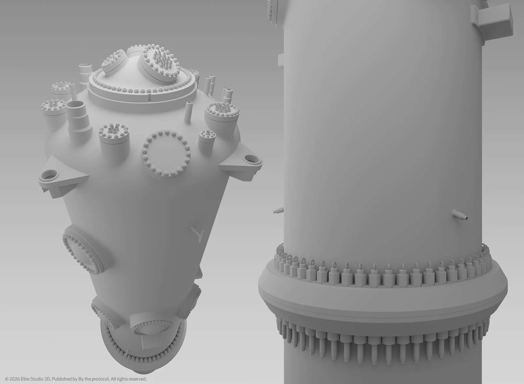
The model separates major access features from smaller penetrations and flange geometry to preserve the documented FSAR-based layout.
The FSAR explicitly states that there are no penetrations in the lower CNV shell or bottom head. That became an important modelling boundary: if a feature was not supported by the documentation, I did not invent it.
Modelling the upper CNV
Most of the visible complexity sits on the upper CNV.
This is where the access openings, nozzles, support features and actuator penetrations have to be arranged in a way that still reads as one coherent system. The upper shell and top head include process piping penetrations, ECCS trip and reset valve penetrations, electrical power and instrumentation penetrations. Fluid system penetrations are described as welded nozzles with safe ends, with the CNV boundary extending to the safe-end definition.
For the model, I separated the work into several visual groups:
- large access openings,
- top head penetrations,
- support lugs,
- refueling flange geometry,
- decay heat removal system nozzles,
- simplified ECCS trip/reset actuator penetrations.
The goal was not to make the vessel look “busy.” The goal was to make the visible arrangement understandable.
Access openings are not decoration
The larger bolted covers on the CNV are some of the most recognizable features, but they are not decorative details.
They represent access and inspection logic.
Steam generator access, pressurizer access, manway access and CRDM access all belong to different maintenance and system relationships. That matters in a reconstruction, because the visual hierarchy has to remain believable. A steam generator access cover should not read the same way as a small process nozzle. A simplified actuator penetration should not compete visually with a major access opening.
In this model, the larger covers were treated as primary visual features. The smaller penetrations were kept secondary.
That hierarchy is important because it helps the viewer understand the vessel before reading any label.
Support and restraint
The CNV is not simply hanging in space. The lower part rests on a support skirt, while the upper CNV is laterally supported by support lugs. The FSAR describes the CNV as resting on a support skirt at the reactor pool floor and being laterally supported on three sides by support lugs that contact restraints in the reactor bay walls.
Those support features are easy to overlook, but they are important to the geometry. They tell us that the containment vessel is not only a pressure boundary. It is also a structural object integrated into the reactor building and reactor pool environment.
For that reason, the support skirt and lugs were modelled as functional geometry, not surface decoration.
DHRS and ECCS-related details
Some of the most delicate modelling decisions were not about large shapes, but about small penetrations. The decay heat removal system nozzles are two NPS 2 Sch. 160 nozzles on the upper CNV, located at elevation 56′-5″ and azimuths 120° and 240°. They are not large access openings, so they had to remain visually modest in the model.
The ECCS trip/reset actuator penetrations required a different approach.
The FSAR describes two reactor recirculation trip/reset valve penetrations on the external side of the CNV upper shell at elevation 58′-11.9″, azimuths 7° and 353°. It also describes three reactor vent trip/reset valve penetrations at elevation 89′-6.85″, azimuths 68°, 188° and 308°, plus one reactor vent trip valve penetration at the same elevation, azimuth 200°.
In the 3D model, these actuator details are simplified. The goal was to preserve their documented location and functional grouping, not to reproduce an unsupported external assembly. The FSAR pressure-boundary figure is a simplified schematic of the valve boundary, not a full external appearance drawing, so the visible geometry was kept restrained.
Working from documentation, not imagination
This reconstruction is based on publicly available FSAR information. That also means there are limits.
Some external appurtenances, brackets, tubing paths or small attachments may exist in real hardware, but if they are not defined or visible in the public FSAR reference material, they were not added as invented detail.
This is a deliberate choice.
The purpose of the model is not to create a fictionalized version of a NuScale module. It is to reconstruct what can be technically supported from public documentation, while making the system readable in three dimensions.
Why the CNV matters visually
The containment vessel is a useful subject because it forces the model to show system thinking.
The CNV is more than a shell, a set of openings, or a pressure boundary; it is the outer vessel that defines the vessel-inside-vessel architecture of the NuScale Power Module.
The reactor pressure vessel sits within it. The reactor pool surrounds it. The containment boundary, passive heat removal path, refueling access, support logic and penetration layout all meet in one object.
That is why this stage took time. The CNV had to be built as a technical object first, and a render subject second.
Next step
The exterior model is now complete.
The next step is to prepare the final render set:
- full containment vessel exterior,
- vertical sectional cutaway,
- selected detail views of the upper head, access openings and penetration layout.
Note
This reconstruction is an independent technical interpretation based on publicly available documentation. It is not an official NuScale Power model, vendor drawing, engineering document, or proprietary representation of the system.
It was created for educational, technical communication, and analytical purposes only, and is not intended for design, engineering, licensing, operational, or safety-related use.
All visual material, 3D reconstruction work, renders, diagrams, and written analysis remain the intellectual property of Elite Studio 3D / By the Protocol unless stated otherwise.
3D Reconstruction By the Protocol CNV Containment Containment Vessel DHRS ECCS FSAR Nuclear Engineering Nuclear Visualization NuScale NuScale Power Module Reactor Design Reactor Pool Reactor Pressure Vessel Refueling Flange RPV Small Modular Reactor SMR Technical Visualization
Last modified: August 21, 2026