

Nuclear Energy in a World of Higher Temperatures
When we talk about the future of nuclear energy, attention is almost always focused on the reactor. New reactor concepts. Passive safety systems. Advanced fuels. Small modular reactors. Higher operating temperatures. Longer fuel cycles.
But a nuclear power plant does not end at the reactor.
Every thermal power plant must solve another, less spectacular task in addition to producing heat: the heat that is not converted into electricity has to go somewhere.
And this final part of the system may become increasingly important in the decades ahead. Not because the reactor itself is becoming less safe, but because the environment that serves as the heat sink may become warmer.
The Reactor Is Only the Beginning of the Energy Path
In a highly simplified form, the energy balance of a thermal power plant can be written as:
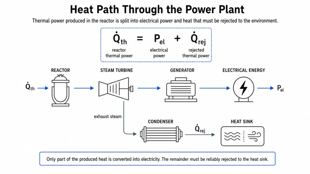
The thermal power produced in the reactor is divided into electrical power and heat that must be rejected to the environment. In a conventional light-water reactor, roughly one third of the generated thermal energy is converted into electricity. The remainder must leave the plant by another path.
The reactor may be operating correctly. The turbine may be operating correctly. All major systems may be available. But if the final link in the energy chain can no longer accept the same amount of heat within permitted conditions, electrical output has to be adjusted.
This is not unique to nuclear energy. It is thermodynamics.
The Quality of the Heat Sink
In a condensing power cycle, the temperature difference between the hot and cold sides of the system matters. The lower the temperature of the heat sink, the more favourable the conditions for condensing steam downstream of the turbine and the greater the potential thermodynamic efficiency.
As cooling-water temperature rises, condenser vacuum may deteriorate and turbine back pressure may increase. The plant must therefore operate under less favourable thermodynamic conditions to maintain the same electrical output. But temperature is not the only parameter. For systems connected to rivers, flow rate also matters.
Heat transfer by a flowing stream of water can be expressed in simplified form as:
If the available mass flow decreases, a greater change in water temperature is required to remove the same amount of heat. At that point, the limitation does not necessarily lie in reactor operation. It may arise from the thermodynamic conditions of the plant or from the permitted thermal loading of the receiving water body.

Cooling-water discharge from Wylfa Nuclear Power Station into the receiving water body.

Cooling-water intake of the former Willington Power Station.

Water sampling at the cooling-water discharge of Big Rock Point Nuclear Power Plant.

Water source and cooling infrastructure of Byron Nuclear Generating Station along the Rock River.
What matters is therefore not only how much heat can technically be transferred from the condenser, but also how much heat may be released into the receiving water body without exceeding permitted temperatures or allowable temperature increases.
A power plant may therefore reduce output during a heat wave even when the reactor itself is operating entirely as intended.
The OECD Nuclear Energy Agency notes that heat waves, droughts and higher cooling-water temperatures have already affected the operation of nuclear power plants, and that warmer cooling water can reduce available electrical output through lower thermodynamic efficiency.
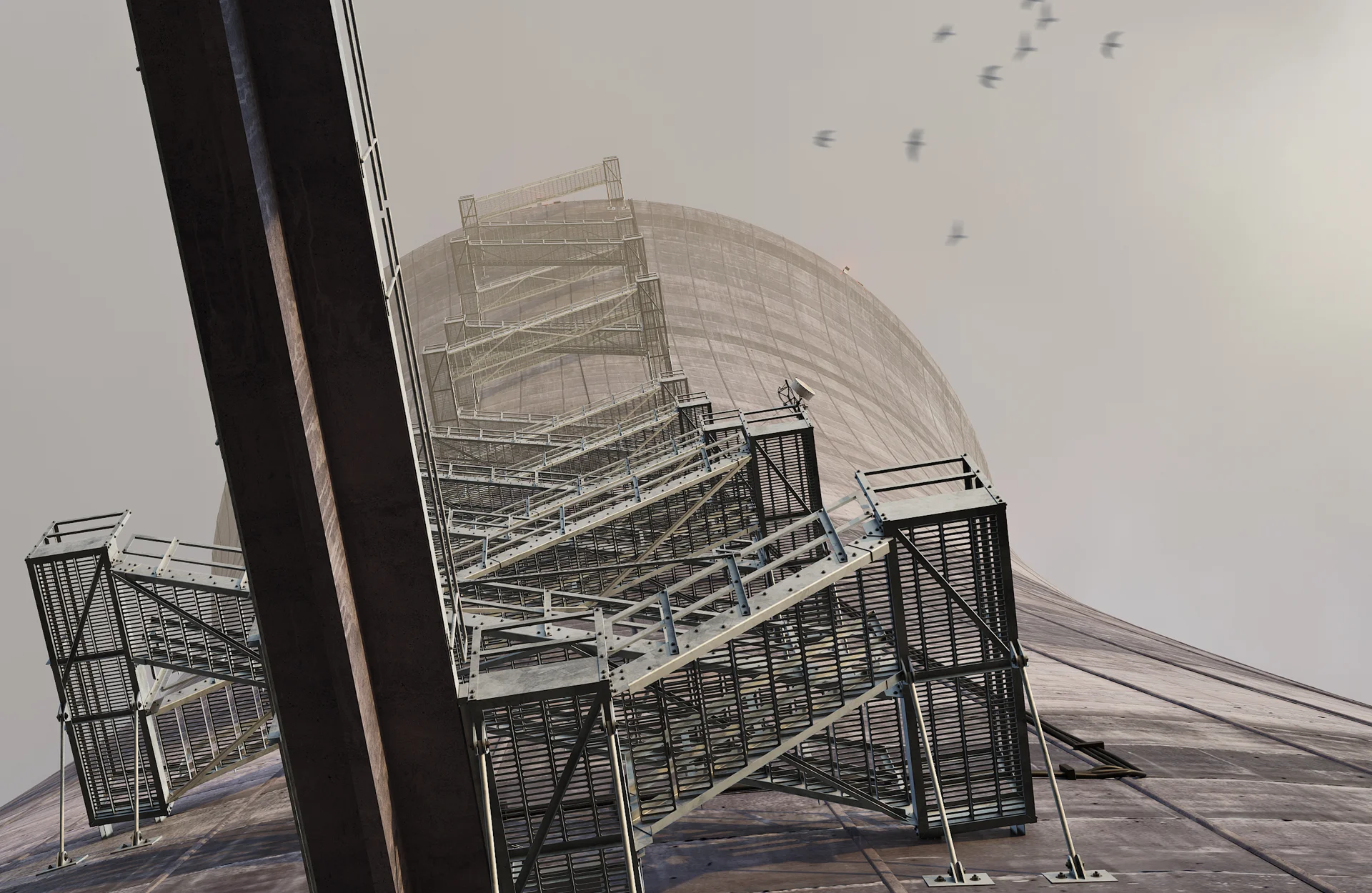
Visualization: Elite Studio 3D / By the Protocol.
A Cooling Tower Does Not Produce Cold
A cooling tower can significantly change the relationship between a power plant and a river or other water source. Instead of transferring most of the waste heat directly to the water body, heat is rejected primarily to the atmosphere through evaporation and heat transfer to the air.
The cooling water then returns, at a lower temperature, to the condenser circuit. But the tower does not create an infinite heat sink. In a wet cooling tower, some of the water evaporates. The system therefore requires make-up water, while a portion of the circulating water must also be discharged as blowdown to control the concentration of dissolved substances.
Cooling performance is strongly related to wet-bulb temperature, which reflects the combined effect of air temperature and humidity. When the air is both hot and humid, the potential for evaporative cooling decreases.
In other words, a cooling tower can substantially reduce a plant’s dependence on the thermal condition of a river, but it does not eliminate the physical relationship between the plant and its environment.
The heat still has to go somewhere.
What About Dry Cooling?
If water becomes a constrained resource, the answer may seem obvious: Use air. With dry cooling, ambient air is the final medium for rejecting heat, so water demand is substantially reduced. But the problem is not eliminated. It is simply moved.
On the hottest summer day, the air intended to serve as the heat sink is also at its hottest. As the available temperature difference decreases, heat rejection becomes more difficult and plant efficiency declines.
Analyses by the U.S. Department of Energy and Idaho National Laboratory have therefore noted that dry-cooling systems can experience significant performance losses at high ambient temperatures.
Hybrid systems attempt to manage this trade-off by reducing water consumption or relying primarily on the dry portion of the system during normal conditions, while making wet cooling available during the most unfavourable periods.
The principle is simple: There is no free heat sink. Water has its limitations. Air has its limitations.
A Production Limitation Is Not the Same as a Safety Limitation
A very important distinction is required here. The condenser cooling system, which supports normal electricity production, is not the same as the systems that provide safety-related removal of decay heat and cooling of safety-significant equipment.
After reactor shutdown, the fission chain reaction stops, but the fuel continues to produce decay heat. Nuclear power plants therefore have specifically designed safety-related heat-removal paths for removing this heat and for cooling structures, systems and components important to safety.
These functions are not the same as those of the normal condenser system, whose primary purpose is to support electricity generation.
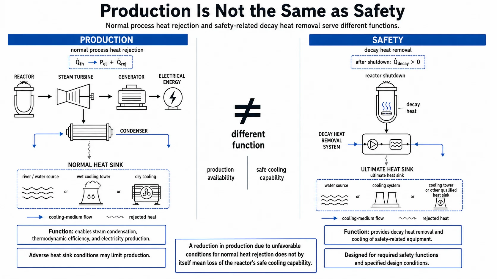
Within the U.S. regulatory framework, General Design Criterion 34 addresses residual heat removal from the reactor coolant system. General Design Criterion 44 requires a system capable of transferring heat from structures, systems and components important to safety to an ultimate heat sink. Such a system must retain the capability to transfer the required heat load under postulated events while accounting for adverse environmental conditions.
Production availability and nuclear safety are not the same issue.
A reduction in electrical output caused by unfavourable conditions for normal rejection of large quantities of process heat therefore does not, by itself, mean that the reactor has lost its capability for safe cooling.
In the future, however, changing climate conditions will have to be considered for both.
Design Conditions Are Changing
A large part of today’s nuclear fleet was designed at a time when historical meteorological and hydrological data could be relied upon heavily when establishing external design conditions. But the future is not necessarily a statistical continuation of the past.
In its treatment of external hazards, the IAEA highlights the importance of extreme temperatures, hydrological events, water availability and heat-sink conditions for the safety of nuclear installations.
In March 2026, the IAEA also published Approaches to Operating Nuclear Power Plants to Mitigate Production Losses Caused by Climate Change and Environmental Hazards, which specifically addresses adaptation of existing nuclear power plant operation to the effects of climate change. Relevant factors include higher temperatures, drought, changes in water availability, and other extreme meteorological and hydrological events.
The OECD Nuclear Energy Agency similarly emphasizes that, because nuclear facilities have long operating lifetimes, climate change needs to be incorporated into site selection, design, licensing and long-term operation.
This represents an important shift. We are no longer asking only:
What were the highest temperatures during the past thirty years?
We must also ask:
What conditions will the system need to withstand over the next forty, sixty or eighty years?
For a power plant with a long design and operating lifetime, the future climate becomes part of the engineering problem.
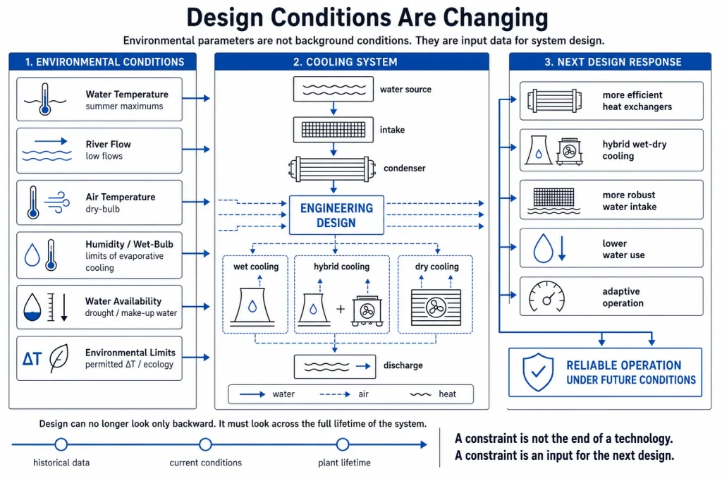
Climate change is not a reason to stop designing. It is a reason to design differently.
The Next Generation of Cooling Systems
If nuclear energy is to become an important part of the future low-carbon electricity system, development cannot remain confined to the reactor island. It will also have to include the heat-rejection system.
This may involve more efficient condensers and heat exchangers, improved wet cooling towers, hybrid wet-dry cooling, alternative sources of make-up water, reuse of treated wastewater, more robust water intakes and water reserves, and adaptive operation of different cooling modes according to prevailing conditions.
There will be no single solution suitable for every site. A coastal plant, a plant located along a major river, a site in a dry inland region and a plant equipped with a closed-loop cooling system face very different constraints.
Cooling-system selection may therefore increasingly become part of site selection itself, rather than an addition to a plant whose location has already been chosen. For some high-temperature reactor concepts, higher thermodynamic efficiency may also help.
If more electricity can be produced from the same amount of generated thermal energy, less heat remains to be rejected to the environment. Another option is the useful application of part of the heat for district heating, industrial processes, hydrogen production or desalination. But cogeneration does not eliminate the fundamental problem either.
Heat demand does not always coincide in time with heat production, and a reliable final path for rejecting excess heat must still exist.
A constraint is not the end of a technology. A constraint is an input for the next design.
A New Nuclear Era Will Need More Than a New Reactor
When we think about the future of nuclear energy, we often imagine more advanced reactor systems. But perhaps one of the greatest engineering challenges of the coming decades will be far less visible.
The question will not only be: How do we produce heat safely?
But also: How do we reject it reliably in a world where the cold sink is no longer so cold?
A heat wave, a river at low flow, or hot ambient air is not a nuclear accident. But they are reminders that no thermal power plant exists independently of the environment into which it must ultimately reject its energy.
A new nuclear era will therefore require more than better reactors. It will also require better cooling systems, more adaptable heat-rejection paths, and designs that consider not only the climate of the past, but the climate across the entire lifetime of the plant.
Author’s Note
This article provides an educational and conceptual explanation of the relationship between the energy balance of a thermal power plant, heat-sink quality, cooling-water temperature, flow rate, meteorological conditions and environmental constraints.
The equations and diagrams shown are intentionally simplified and illustrate basic physical and functional relationships involved in heat rejection. They do not represent calculations of the actual heat balance, design values, operating parameters or permitted limits of any specific power plant.
The cooling-system representations are conceptual and do not depict the process configuration of any individual facility. Actual heat-rejection capability depends on plant design, local hydrological and meteorological conditions, operating procedures, and applicable environmental and licensing requirements.
Sources and Further Reading
OECD Nuclear Energy Agency (NEA)
Climate Change: Assessment of the Vulnerability of Nuclear Power Plants and Approaches for their Adaptation.
IAEA — Climate Change and Nuclear Power 2022
International Atomic Energy Agency (IAEA)
TECDOC-2119 je Approaches to Operating Nuclear Power Plants to Mitigate Production Losses Caused by Climate Change and Environmental Hazards.
International Atomic Energy Agency (IAEA)
Meteorological and Hydrological Hazards in Site Evaluation for Nuclear Installations.
U.S. Nuclear Regulatory Commission (NRC)
10 CFR Part 50, Appendix A — General Design Criterion 34, Residual Heat Removal, ter General Design Criterion 44, Cooling Water.
Idaho National Laboratory / U.S. Department of Energy
Comparison of Advanced Cooling Technologies Efficiency and Water Consumption in Nuclear Power Plants
Note on Images and Visualizations
Third-party photographs used in this article are reproduced in accordance with their applicable licence terms. The author, source and licence are identified with each individual photograph. The featured image is used under an appropriate commercial licence from the provider.
3D visualizations by Elite Studio 3D / By the Protocol are original work created for technical and educational illustration of the systems discussed.
Diagrams and system representations were prepared specifically for this article as simplified conceptual explanations. They do not constitute technical documentation, engineering drawings, or the configuration of any specific power plant.
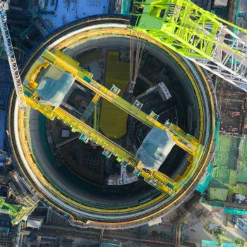
Featured image: iStock — Doel Nuclear Power Plant, Belgium. Peter Braakmann, Creative.
Big Rock Point, Michigan. Source: U.S. Department of Energy / ENERGY.GOV, Wikimedia Commons. Public domain.
Byron Nuclear Generating Station, Illinois. Photo: Ben Jacobson. Source: Wikimedia Commons. Licence: CC BY 2.5.
Wylfa Nuclear Power Station, Wales. Photo: Eric Jones / Geograph. Source: Wikimedia Commons. Licence: CC BY-SA 2.0.
Willington Power Station, Derbyshire. Photo: Phil Myott / Geograph. Source: Wikimedia Commons. Licence: CC BY-SA 2.0.
climate change climate resilience condenser cooling systems Cooling Tower cooling water temperature Decay Heat dry cooling Heat Rejection heat sink hybrid cooling nuclear energy nuclear power plant design nuclear safety river flow thermal balance thermal hydraulics ultimate heat sink wet cooling wet-bulb temperature
Last modified: August 14, 2026