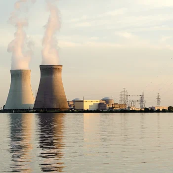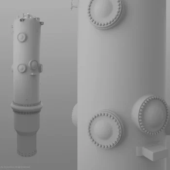


This article is the first instalment in a multi-part By the Protocol series examining how containment functions, boundaries and supporting structures are defined across different reactor designs.
Why a Dome Does Not Reveal the Credited Accident Boundary
In public discussions of nuclear power plants, the terms reactor building, containment, containment building and dome are often used as though they meant the same thing.
They do not.
The confusion is understandable. A nuclear power plant is often represented in public by a large concrete structure surrounding the reactor. It may be round, massive, visually dominant and easily recognisable. For many people, that image simply becomes “the containment”. But technical systems are not classified by appearance. They are classified by function.
Containment is not merely a large building around the reactor. It is a credited safety boundary. More precisely, it is an engineered boundary intended to limit the consequences of an accident, designed, analysed and tested to retain its function under defined accident conditions.
By contrast, the reactor building forms part of the plant’s operational and support infrastructure. It provides space, access, equipment layout, lifting capability, maintenance routes, ventilation zoning, fire safety and logistical routes for personnel and components. In some designs, it may also support radiological control or secondary containment functions. However, this does not make every structure around the reactor a credited leak-tight pressure boundary.
Containment as a Safety Function
Containment is required because, in addition to the barriers that retain radioactive material during normal operation, a reactor system also needs a credited boundary for limiting the consequences of an accident.
Design-basis accident analyses, such as those for a loss-of-coolant accident or a steam release inside containment, demonstrate that this boundary must maintain structural integrity under specified pressure and temperature conditions, limit releases, and enable the isolation of pathways that could otherwise bypass the containment boundary.
This is why containment is not simply a wall.
It is a system boundary with defined requirements. Its function is provided by concrete or steel structures, a leak-tight liner, sealed penetrations, containment isolation valves, hatches, seals and airlocks. Its ability to perform that function is demonstrated through testing programmes, while the requirements derive from the plant’s design and licensing basis. The physical structure matters, but the safety function determines what the structure must provide.
A Dome Does Not Tell the Whole Story
A large concrete structure may look like containment. A reactor building may surround the reactor. A photograph may show a crane, a circular wall, hatches and internal platforms. But without knowing the plant design and its licensing basis, a photograph alone cannot identify the credited accident boundary.
The practical question is therefore not: What does it look like?
The practical question is: What function is it credited to perform?
The Reactor Building as Infrastructure
The reactor building has a different role.
It forms part of the plant’s operational and support infrastructure. It provides access to equipment, maintenance space, lifting and handling routes, laydown areas, ventilation zoning, radiation protection and fire protection measures, and logistical routes for equipment, components and personnel.
A polar crane or overhead travelling crane, for example, is not part of the leak-tight containment boundary, although it may be installed inside it or in spaces functionally associated with it. Large components must be installed, inspected, removed and maintained. Refuelling, reactor vessel head lifts, component replacement and outage work therefore require physical access and suitable heavy-load handling capability.
This is why reactor-building interiors are often highly complex. They are not empty shells. They are working spaces.
They contain structures, equipment, platforms, lighting, cable routes, ventilation systems, hatches and access routes. Some of these elements serve plant operation, others support maintenance or radiological control, and some are directly associated with containment functions.
But support infrastructure is not the same as the credited leak-tight boundary for retaining radioactive material under accident conditions.
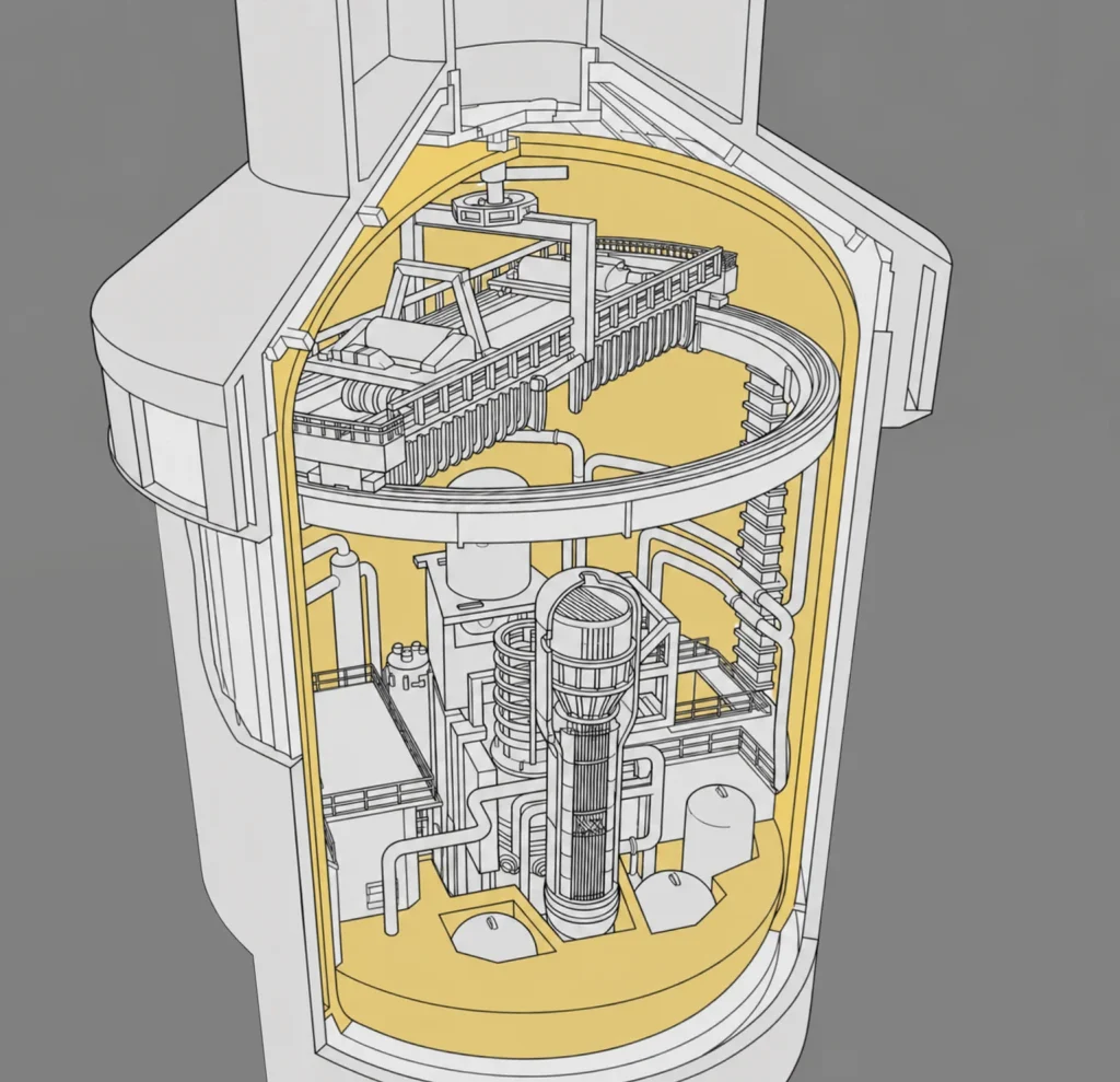
This distinction is especially important when interpreting photographs, 3D reconstructions and simplified diagrams. A drawing may show the entire building around the reactor, while the containment boundary comprises only part of the structure shown. Some designs may include primary and secondary containment, an annulus, or other surrounding structures with different functions.
Terminology may vary by reactor type, country, design generation and the terminology used in the plant’s licensing documentation. The principle remains the same: classification must follow the credited function, not visual impression.
Penetrations Show Why the Distinction Matters
The containment boundary is perhaps best understood at the points where penetrations cross it.
A penetration is not merely an opening through a wall. It is a controlled passage through a safety boundary that must provide the required connection without negating the purpose of that boundary.
Pipes, cables, ventilation ducts, instrumentation lines and other system interfaces must cross the containment boundary. The boundary must also accommodate personnel airlocks and equipment hatches. Every such crossing presents the same challenge: the plant requires the connection, but the boundary must still retain its ability to perform its safety function.
This is why containment penetrations are closely tied to leak-tightness and isolation.
If a pipe crosses the containment boundary, the design must define how the penetration assembly is sealed, how it performs under accident conditions and how the flow path can be isolated when required. If cables cross the boundary, their penetration assemblies must preserve its leak-tightness and function. Personnel airlocks and equipment hatches must provide access without compromising the leak-tightness or containment function of the credited boundary.
At this point, the distinction between the building and containment is no longer merely terminological.
If we identify the wrong structure as the containment boundary, we will also misinterpret the penetrations. A drawing may appear to show “pipes through the building”, but the technical question is whether those pipes cross the credited containment boundary and which sealing and isolation requirements apply to them.
The containment boundary is therefore not merely a shape. It is a controlled interface.
Why Public Language Often Gets It Wrong
Public communication often reduces nuclear facilities to recognisable images. A dome is easy to show. A containment function is harder to explain.
Such simplification is not always harmful, but it can become misleading when visual labels replace technical meaning. If every large structure around the reactor is called containment, the public may misunderstand which part of the plant is actually credited to maintain integrity and leak-tightness under the pressure and temperature conditions associated with an accident, and to limit radioactive releases.
It can also lead to incorrect conclusions when reactor designs are compared.
A facility housing a small modular reactor may not resemble a conventional large dome. A boiling water reactor may have a different containment arrangement from a pressurised water reactor. Some designs include secondary containment, filtered containment venting, or other associated structures and systems. Terminology may also differ for the reactor building, containment building, primary containment and surrounding structures.
The absence of a familiar dome does not mean the absence of a containment function. The presence of a large building does not, by itself, identify the credited boundary.
Nuclear design does not begin with architecture. It begins with function.
A Practical Rule
A simple rule helps avoid confusion:
If a boundary is designed, analysed, tested and credited to maintain structural integrity and leak-tightness under defined accident conditions and to limit radioactive releases, it is a containment boundary.
If a structure primarily supports access, operation, maintenance, ventilation zoning, load handling, fire safety, and the spatial arrangement of equipment and systems, it is a reactor building or supporting structure.
The exact terminology depends on the plant design and its licensing basis. The method of interpretation, however, must remain disciplined. A name, a silhouette, or the impression created by a massive, round or domed structure is not sufficient for classification. The decisive factor is its credited function.
Containment is not merely the place where the reactor is located. It is a boundary that must retain its meaning even when normal operating conditions can no longer be assumed.
Notes on Images and Materials
Cover photograph: Licensed photograph from iStock, used as an illustrative view of the construction of a reactor or containment structure and its associated lifting infrastructure. The photograph is not used as a plant-specific technical reference. Classification of containment boundaries depends on the plant-specific design and licensing basis.
3D cutaway: Original visual work by Elite Studio 3D / By the Protocol, used as a simplified functional illustration of the distinction between the reactor building and the containment boundary.
All remaining visual material, 3D reconstructions, renders, diagrams and written analyses are the intellectual property of Elite Studio 3D / By the Protocol, unless otherwise stated.
accident boundary Containment containment boundary containment isolation containment penetrations leak-tight boundary nuclear safety reactor building reactor systems safety functions
Last modified: August 21, 2026