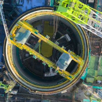


From Steel Containment Vessel Inspections to CILRT, Local Tests and Acceptance Criteria
If we began demonstrating containment leak tightness at the pressure gauge, we would be starting too late. Before the steel containment vessel is brought to the test pressure, someone must know the condition of its pressure boundary. Someone must inspect the surfaces, welded joints, bolts, penetrations and transitions between accessible and embedded portions. They must identify damage to the protective coating, traces of condensate runoff, incipient corrosion, an unusual indication or a change that was not present during the previous inspection. Each finding must be marked, photographed, evaluated and linked to a traceable record.
This work does not take place only in the field. The route to an inspection involves work orders, radiation work permits, a pre-job briefing (PJB), equipment checks and permits for work at height and in confined spaces. Only when the inspection scope, the condition of the structure and the configuration of the pressure boundary are known can a leakage test answer the question it is intended to address. Even then, however, it does not answer every question.
Containment integrity is not demonstrated by a single test. It is demonstrated through a chain of inspections, measurements, local tests, engineering evaluations, corrective actions and records. Each link in that chain answers a different question.
One Boundary, Several Different Questions
Integrity and leak tightness are closely related, but they do not mean the same thing. Structural integrity describes the ability of the pressure boundary to retain its geometry, load-bearing capacity and continuity under the anticipated loads. Leak tightness indicates whether leakage through the entire boundary and its individual penetrations is limited to the allowable value. Isolation functionality requires something more: valves, seals, airlocks and other closure devices must perform their intended function in the configuration in which they would be needed during an accident.
| Question | Main type of evidence | What it verifies |
| Is the pressure boundary sound in terms of its material and structural condition? | Inspection program, visual examinations and other nondestructive testing | Corrosion, damage, deformation, and the condition of welds, bolts, coatings and critical areas |
| What is the overall leakage rate of the entire boundary? | Integrated leakage testing; the publicly available paper by Pušnik and Guliš uses the abbreviation CILRT | The integrated leakage rate of the entire boundary at a specified test configuration and pressure |
| Where does an individual local path leak, and at what rate? | Type B and Type C local tests, often referred to collectively as LLRT | Penetrations, their sealing boundaries, airlocks and isolation valves |
| Is the degradation identified being managed over the long term? | Trending, the corrective action program, repair or replacement, and reinspection | Changes in condition over time and the effectiveness of the actions taken |
A leakage test therefore does not replace a structural inspection. A structural inspection, in turn, does not by itself measure the actual overall leakage rate. Nor does a local test of an individual valve establish how much the entire containment boundary leaks. Only together do they provide a technical picture that can be assessed against acceptance criteria.
Why Geometry Determines How an Inspection Is Performed
At Krško Nuclear Power Plant (NEK), the primary containment pressure boundary is a freestanding Class MC (metal containment) steel vessel. It is surrounded by a reinforced-concrete shield building, with an annular space, or annulus, between the two. The steel vessel has an internal diameter of approximately 32 meters and an overall height of approximately 70 meters. It consists of a cylindrical section, a hemispherical dome and a torispherical bottom head.
This arrangement is not merely a geometric feature. It directly determines which surfaces are accessible, from which side they can be inspected and where areas requiring particular attention arise. Because most of the steel vessel is not in direct contact with the external concrete structure, a large proportion of its surface is accessible both from the inside and from the annulus. The situation is different at the lower embedded portion and at the transition between the embedded and freestanding portions of the vessel. This is precisely where the moisture barrier is installed, a sealing barrier intended to prevent moisture from entering the difficult-to-access interface between steel and concrete.
The publicly available paper by Lenart Pušnik and Matija Guliš, Implementation of Containment Inspection Program at NPP Krško, relates this spatial arrangement to the actual implementation of the inspection program. Its value lies not only in its description of the requirements. It also shows access arrangements, limitations, the sequence of work, the equipment used, documentation practices and specific findings accumulated over years of program implementation.
A Program, Not a Single Event
The Containment Inspection Program (CIP) is part of the broader inservice inspection (ISI) program. For Class MC steel containment vessels, it is based on the requirements of ASME Section XI, Subsection IWE. The publicly available paper states that the program at NEK is organized into ten-year intervals, each divided into three inspection periods. By the end of each interval, the full required scope of examinations must have been completed, and the results retained as part of the long-term record of the component’s condition.
The program therefore defines more than what needs to be examined. It also establishes responsibilities, plans, identification drawings, procedures, personnel qualifications, methods for evaluating results and record retention. An inspection is not a standalone activity that ends when the inspectors leave the area. It forms part of a structure extending over time, in which today’s finding is compared with the previous one and the future scope may be expanded if a condition requiring augmented inspection is identified.
The ten-year CIP interval is not the interval between CILRTs. These are two distinct types of verification with different purposes, linked at important points. CIP monitors the material and structural condition of the containment vessel, whereas CILRT measures the integrated leakage of the pressure boundary in a specified configuration. Material condition and measured leak tightness are related, but they cannot be demonstrated by a single method.

The First Part of the Inspection Begins Before Entry
Much of the quality of an inspection is established before the inspector sees the first steel plate.
In the implementation plan, components and areas are divided into practical groups, such as the inside of the containment vessel and the annulus. Work orders are prepared for the selected work window and include drawings, checklists, applicable procedures and work permits. The scope must be coordinated with outage activities, radiological conditions, accessibility and other work taking place in the same area.

When entering the annulus, simply knowing what needs to be inspected is not enough. Its characteristics mean that it is classified as a confined space, where air quality must be checked before entry. The paper describes entry by a two-person team, the use of lamps and headlamps, fall-protection equipment and mandatory familiarization with the rescue plan. The firefighters responsible for rescue are notified before entry and after exit. Access must also be scheduled in coordination with the radiological conditions near the fuel transfer canal.
The work often takes place on ladders, platforms and elevated access routes. Personal protective equipment, fall protection and securing inspection equipment, dosimeters, lamps and other equipment are therefore not optional additions to the inspection. They are prerequisites for performing it without creating a new hazard for people or the facility.
A pre-job briefing is held before work begins. The team checks the inspection scope, requirements, procedures, work permits, and the safety and inspection equipment needed. Inspections are usually performed by a two-person team: an ISI engineer and an ISI technician or a contracted ISI inspector. Work begins only once the shift supervisor has authorized the work order for execution and it has been activated through the prescribed process.
This is the first important step beyond an oversimplified understanding of inservice inspection: an inspection does not begin with looking. It begins with establishing the conditions under which an observation can be reliable.
Following the Steel Boundary
Accessible surfaces are inspected from inside the vessel and from the outside, in the annulus. The publicly available paper describes a circumferential inspection pattern progressing from lower to higher elevations. Along the route, the two inspectors identify the accessible plates, follow the checklist and document any relevant indications.
When the route takes them past another component within the program scope, examination of the plates forming the steel shell is temporarily interrupted so that the required examination of that component can be performed. A bolted connection, for example, falls into a different category and is subject to a more stringent examination requirement than a generally accessible surface. This organization reduces the total time spent in a radiologically controlled or restricted area without losing control of the scope.
The walls formed by the rows of steel plates are not the only features that matter along the route. Penetration areas, welded joints, pressure-boundary bolts, coatings, sealed transitions and other locations where the structural geometry changes or where the environment allows degradation to develop are also examined.
At the end of the work, the equipment is checked for completeness and the item count is verified against the initial count. The team confirms whether all planned locations and components have been examined. This is followed by closure of the work order and a post-job briefing to identify any safety deviations or concerns, as well as good practices.
An inspection is thus both a physical route and a traceable process. If it cannot be demonstrated where the inspector went, what they saw and what they did in response to a finding, the observation alone is not enough.
Assessing the General Condition or Taking a Closer Look
Different methods do not look for the same phenomena or provide the same level of detail. A general visual examination (GVE) is intended to assess the overall condition of accessible surfaces. On coated or painted areas, inspectors look for peeling, blistering, coating disbondment, discoloration and other signs of degradation. On uncoated surfaces, cracks, wear, pitting or general corrosion, notches, dents and other irregularities are important.
VT-1 is a more detailed visual examination. The publicly available paper specifies it for pressure-boundary bolting, such as flange bolts, and for areas requiring augmented inspection. It requires suitable illumination, a limited viewing distance and a verifiable ability to resolve the required detail. It may be performed directly or using remote equipment, provided that the camera or optical system is demonstrated to deliver equivalent or better resolution.
If a visual examination identifies a relevant condition, additional nondestructive testing (NDT) is required. Liquid penetrant testing (PT) is used to detect surface-breaking discontinuities. Magnetic particle testing (MT) detects surface and near-surface discontinuities in ferromagnetic materials. Ultrasonic thickness measurement allows material loss to be evaluated in selected areas and measurements to be tracked on a defined grid. The publicly available paper also lists vacuum-box bubble testing and acoustic emission among the possible supplementary methods. Such methods can help identify a local leak or an area requiring further investigation; a new method must be appropriately qualified before use.
One further point matters: a method does not deliver the final judgment on its own. It produces data that a qualified person must interpret correctly.
An Indication Is Not Yet a Defect
In 2016, a crack-like indication was observed at the junction between the equipment hatch penetration and its reinforcing ring. Its appearance suggested that it was in the weld area. Further examination revealed a different explanation.
A piece of welding slag had remained on part of the weld after fabrication and had been painted over. Over time, it loosened and created the appearance of a crack. When the slag was removed, an undamaged weld was revealed beneath it. Surface corrosion was present at the exposed location. It was removed, and the area was cleaned and recoated.
This is a small example, but an important one in terms of methodology. An inspector must neither disregard an indication nor immediately declare it an unacceptable defect. It must first be identified, documented and evaluated using a method that distinguishes appearance from the actual condition of the material.
Such an inspection is therefore not based on how dramatic the finding appears. It is based on the quality of the process leading from an observation to a technically justified conclusion.
When the Surface Is There but Access Is Not
Part of the steel vessel is obscured by internal concrete structures. In 2022, NEK attempted to obtain additional information about otherwise inaccessible surfaces using a remotely controlled inspection crawler equipped with a camera and magnetic wheels.
The attempt was only partially successful. The uneven surface of the concrete wall and, in places, an excessively narrow gap between the structures limited the crawler’s movement. This example clearly illustrates the practical value of remote technology. An inspection crawler can carry a camera where a person cannot go, but it cannot eliminate the geometry that makes an area difficult to access.
A partially successful inspection is therefore not a failure without value. It establishes which areas were reached, where the limitations of the equipment lie and what solution may need to be developed for a future inspection. A method’s limitations are also technical information.

In his technical review of this article, Lenart Pušnik adds: The surface in question was subsequently examined from the accessible inner side using ultrasonic wall-thickness measurement. The measurement confirmed the design condition. In this case, ultrasonic testing was an alternative to visual examination, but this inspection method was more time-consuming.
A Moisture Barrier at an Important Transition
For a freestanding Class MC steel containment vessel, the transition between the lower embedded portion and the freestanding portion is particularly important. In this area, the moisture barrier limits water ingress into the gap between steel and concrete, thereby reducing the potential for hidden corrosion.
At NEK, an elastic Thiokol sealant is used on the inside of the vessel, while cork is used on the outside. The barrier must limit moisture ingress while accommodating the deformation that occurs during operation and pressure testing.

Its location is demanding. It is exposed to spills, condensate, washing and decontamination, as well as mechanical effects during equipment movement. With aging, the sealant may lose flexibility and adhesion. The surface behind the barrier is not directly visible, so corrosion could develop without an obvious external sign.
According to the publicly available paper, the first localized cracks in the inner sealing barrier were recorded in 2016. From then on, additional inspections were performed during every outage to monitor the existing condition and identify new changes. After 2018, the cracks were temporarily protected with a resistant coating to limit potential water ingress. Small areas of incipient surface corrosion above the barrier were also repaired.
The inspection results from the 2022 outage showed that the existing condition was not suitable for continued long-term operation without replacement. An action plan was prepared, and replacement with an equivalent solution was selected. Because the barrier runs around the inner circumference of the steel vessel, and replacing it all at once would obstruct transport routes, the work was divided across several outages.
During the 2024 outage, the barrier was replaced in two areas totaling 30 meters in length. Once the old sealant had been removed, the previously concealed steel surface could be inspected directly. Surface corrosion was observed, with no visible progression into the depth of the material. Most of the exposed surface showed no corrosion, and the adhesion of the old sealant to the metal was generally good. Based on these findings, the authors of the publicly available paper concluded that the replacement had been timely: the existing material was no longer performing its sealing function effectively, but corrosion damage had not developed over a large area and the integrity of the steel vessel had not been compromised.
This is one of the clearest examples of what an inspection program actually means. It is not a matter of waiting for failure. It is a sequence:
Observation → additional inspection → monitoring over several outages → interim action → long-term decision → replacement → direct confirmation of the condition of the concealed surface.
The program did more than show that the integrity of the steel vessel had not yet been compromised. It enabled action before localized degradation could develop into more serious damage.
Leak Tightness of the Entire Boundary and CILRT
When leak tightness is discussed, attention often turns first to integrated leakage testing. The publicly available paper on NEK uses the abbreviation CILRT (Combined Integrity Leak Rate Test). The U.S. regulatory framework in 10 CFR Part 50, Appendix J, defines a Type A test as a measurement of the overall integrated leakage rate of the primary containment. In terms of its purpose, CILRT corresponds to this test.
The publicly available paper states that CILRT is the responsibility of Operations, that it is performed in accordance with the plant’s own procedures and Technical Specifications, and that the vessel is brought to the design gauge pressure of 3.15 kp/cm², approximately 0.309 MPa. Within the period covered by the paper, the most recent test reported was performed in 2016.
A public record issued by the Slovenian Nuclear Safety Administration (SNSA) on 21 November 2024 states that the CILRT interval was extended from 10 to 15 years. The Technical Specifications also require visual checks of accessible surfaces five times during the fifteen-year period, or once every three years, and an inspection of accessible external and internal components before each CILRT. The change applies to the pressure-testing program and its associated visual checks; it does not change the ten-year interval structure of the CIP under IWE.
In a technical clarification, Lenart Pušnik explains that CIP inspections are performed independently of the pressure test and the visual checks or walkdowns carried out by production or operations personnel. It is the pressure test and these walkdowns that are specified in the Technical Specifications. The personnel performing walkdowns do not hold the formal VT or NDT inspector qualifications held by personnel in the inservice inspection (ISI) department. Under the CIP, 100% of the containment is inspected during each inspection period, while all penetrations, bolting and other prescribed components are examined once per interval. In practice, this means that approximately 50% of the steel shell and a number of penetrations are examined during each outage; six CIP inspections are thus performed over ten years, or one interval. CIP is an integral part of the ISI program, which is addressed elsewhere in the Technical Specifications.
For the 2016 test, the table in the publicly available paper gives an acceptance criterion of 0.75 La, or 0.150% per 24 hours. La denotes the maximum allowable leakage rate at pressure Pa, as specified in the Technical Specifications. The upper confidence limit (UCL) is 0.034% per 24 hours. The direct ratio of 0.034 to 0.150 is approximately 22.7%. The table nevertheless reports a final result of 26.35% of 0.75 La; the accompanying footnote explains that this includes leak penalties from local tests of penetrations that had not been prepared for the CILRT configuration. Because the individual values of these penalties and the calculation method are not published in the public source, the final percentage cannot be independently reconstructed in greater detail from the available data.

The result can only be understood together with the test configuration, the method used, the measurement uncertainty and the acceptance criterion. A number without this context may sound precise, but it does not tell us enough.
This is precisely why Appendix J requires an inspection of accessible internal and external surfaces before a Type A test. If there is evidence of structural degradation that could affect integrity or leak tightness, the condition must first be addressed. Pressurization is not a substitute for visual examination, nor is it a method for determining whether a coating is damaged, whether moisture is trapped behind a sealed transition or whether material loss has begun in a localized area.
CILRT answers the question of how much the entire tested boundary leaks in a specified configuration. On its own, however, it does not identify which individual path is responsible for local leakage, nor does it replace long-term monitoring of material condition.
Local Leak Tightness of Penetrations, Airlocks and Valves
The containment vessel cannot be an uninterrupted steel shell. Pipes, electrical conductors, instrumentation connections, ventilation paths and access routes for people and equipment must pass through it. Each penetration must retain its required pass-through function while remaining part of the containment pressure boundary.

This is where local leakage tests come in. Appendix J distinguishes between Type B and Type C tests. Type B tests address the local pressure-retaining and sealing boundaries of penetrations, including airlocks and their sealing surfaces. Type C tests measure leakage through containment isolation valves. During a local test, pressure is applied to an individual component or test volume, allowing the condition of a specific leakage path to be determined.
In technical usage, Type B and Type C local tests are often referred to collectively as LLRT (Local Leak Rate Test). In this article, the term is used as a generic designation for the type of test, not as the title of a specific internal NEK procedure. But “local” does not mean “less important.” The entire containment boundary is made up of precisely these local details. An airlock seal, an isolation valve seat or a penetration boundary is small compared with the surface of the dome, yet each may provide a direct path from one side of the pressure boundary to the other.

Local and integrated tests therefore do not duplicate one another. They complement each other. CILRT shows the behavior of the entire tested boundary, while LLRT allows individual paths to be monitored, their behavior to be compared over time and action to be taken on a specific component.
The publicly available table of CILRT results includes a footnote for the 2007 and 2016 measurements stating that LLRT leak penalties were included for penetrations that had not been prepared for the CILRT configuration. This is an important detail: it shows that the final result cannot be read simply as the directly measured leakage of the entire boundary in a single configuration. Paths whose contribution was determined locally and then incorporated into the result must also be taken into account.
An Acceptance Criterion Is More Than a Line Beneath the Result
An acceptance criterion is essential in leakage testing, but it is not, by itself, the entire program.
The result must be related to the allowable leakage rate, test pressure, component configuration, measurement uncertainty, any local contributions and the history of previous results. If an individual local path exceeds a specified criterion, evaluation, repair or adjustment, and retesting follow in accordance with the applicable requirements. If an adverse trend emerges over several cycles, that can be important information even when an individual result has not yet exceeded the acceptance criterion.
Demonstrating performance is therefore not a binary “pass or fail” snapshot. It is the management of technical evidence over time.
The division of responsibilities also matters. The publicly available paper states that the steel containment vessel is covered by the inservice inspection department under the CIP, while CILRT, other pressure tests and walkdowns fall within the remit of Operations. The concrete shield structure is covered by the civil maintenance department. The programs have different responsible organizations and purposes, but their evidence jointly supports the assessment of the containment system. This is an interdisciplinary task in which no single department holds the entire picture.
Evidence Must Remain Traceable
Once an inspection is complete, the checklist data are transferred to a digital report. Photographs and other recordings are retained in the inspection documentation. If a deviation from the expected condition is identified, the corrective action program is initiated and the necessary actions are defined. A final report is prepared after the work orders for the outage have been closed. The publicly available paper also mentions that a copy of the report is sent to the Slovenian Nuclear Safety Administration.
This administrative sequence is not a bureaucratic addition to the technical work. It ensures that a finding does not remain solely in the memory of the person who observed it. A photograph is assigned a location. An indication receives an evaluation. A corrective action receives a traceable record. The next inspection gains a baseline for comparison.
For a component whose required service life is measured in decades, it must be possible to trace not only its condition today, but also how that condition has changed and why a particular action was selected.
Containment Is Not Verified Just Once
The outer concrete dome is the most recognizable visible part of a nuclear facility. Yet the work of demonstrating the function of the primary steel containment boundary hidden inside it is almost entirely invisible.
Conditions must be observed early enough. An indication must be distinguished from a defect. It must be known which surfaces are inaccessible and what the method used can or cannot reveal about them. Localized degradation must be monitored before it progresses to significant material loss. Individual leakage paths must be tested, and the entire boundary evaluated in a configuration and at a pressure that are technically meaningful. Every result must be comparable, explainable and traceable.
A successful CILRT is therefore not the end of the story. It is one of its most important pieces of evidence.
It is preceded by planning, competence, access, illumination, an examined surface and a correctly evaluated indication. Alongside it are local tests of penetrations and isolation valves. After it remain a record, a trend and a decision about what must be checked, repaired or replaced before the next interval.
A containment boundary is not reliable because it is large. It is reliable because its condition is not assumed.
It is demonstrated. Again and again.
Scope Note
This article is based on publicly available sources and technical clarifications provided by the reviewer. It does not use internal procedures, instructions, documentation or unpublished operating data. Individual practical explanations added to the draft by the reviewer are clearly identified in the text as technical clarifications; they do not represent an official position or institutional endorsement.
The original text, 3D reconstruction, renders and diagrams are the work of Nina Lovišček under Elite Studio 3D / By the Protocol.
Source of all three photographs: L. Pušnik and M. Guliš (2024), Implementation of Containment Inspection Program at NPP Krško.
References
Pušnik, Lenart, and Matija Guliš. Implementation of Containment Inspection Program at NPP Krško. Proceedings of the 14th International Conference of the Croatian Nuclear Society, 2024, Paper No. 101.
U.S. Nuclear Regulatory Commission. 10 CFR Part 50, Appendix J: Primary Reactor Containment Leakage Testing for Water-Cooled Power Reactors.
U.S. Nuclear Regulatory Commission. Regulatory Guide 1.163, Revision 1, Performance-Based Containment Leak-Test Program. June 2023.
Slovenian Nuclear Safety Administration. Amendment to TS SR 3.6.1.7 to extend the CILRT interval. 21 November 2024, letter No. 3570-4/2023/6. NEK topic page.
CILRT CIP containment leak tightness electrical penetrations inservice inspection ISI Krško Nuclear Power Plant leakage testing LLRT moisture barrier NDT nuclear containment nuclear safety steel containment vessel structural integrity ultrasonic thickness measurement
Last modified: October 12, 2026