When Documentation Becomes Space
A documentation-driven reconstruction of a NuScale-style SMR core, focused on the spatial relationship between fuel assemblies, control rod assemblies, in-core instrumentation, upper core structures, and the wider logic of compact reactor architecture.
• May 25, 2026

Reconstructing a NuScale-style SMR core through system logic, geometry, and public documentation
I did not approach this project as another visual representation of a reactor. The goal was different. I wanted to understand the core of a NuScale-style small modular reactor from the inside out and translate that understanding into a spatial, readable 3D structure.
A reactor core is often shown as a simplified block, a symbolic arrangement of fuel assemblies, or a technical diagram reduced to its basic function. But when the system is reconstructed in three dimensions, the core stops being an abstract technical term.
It becomes a spatial system. Not architecture in the decorative sense, but architecture as structure, alignment, hierarchy, constraint, access, measurement, control, and function.
Every opening matters. Every repeated position matters. Every modified position matters. Every component belongs to a larger internal logic.
A note on the word “small”
The word “small” in SMR needs careful handling.
In this context, small does not mean simple. It does not mean visually small in an everyday sense, and it does not mean that the internal system is reduced to something easy to understand.
In SMR terminology, small primarily refers to lower power output compared with large conventional nuclear power plants, together with modular design and deployment logic.
The engineering reality is more demanding than the word may suggest.
A NuScale-style SMR still contains a dense internal reactor architecture. Fuel assemblies, control rod assemblies, in-core instrumentation, support structures, flow paths, vessel interfaces, and upper internal components all have to coexist within a compact system.
Compactness does not remove complexity. It concentrates it.
This is why the reconstruction is not only a matter of modelling recognizable parts. It is a matter of understanding how those parts relate to one another inside a tightly integrated reactor architecture.
From documentation to geometry
The reconstruction began with public technical documentation. Before modelling, there is reading. Before geometry, there is interpretation.
A drawing can provide a section, a pattern, a component name, or a dimensional clue. But documentation does not automatically become spatial understanding. That translation has to be built carefully.
For this core reconstruction, the main focus was on the arrangement of fuel assemblies, the relationship between control rod assemblies and the upper core structure, the position and function of in-core instrumentation, and the internal structures that give the core its physical order.
The aim was not to produce a visually dramatic reactor image. The aim was to understand what the documentation implies in space.
Where does one component pass through another? What is guided? What is fixed? What must remain aligned? Which positions are repeated, and which positions are modified because they serve a different purpose?
These questions are where the model begins to become useful.
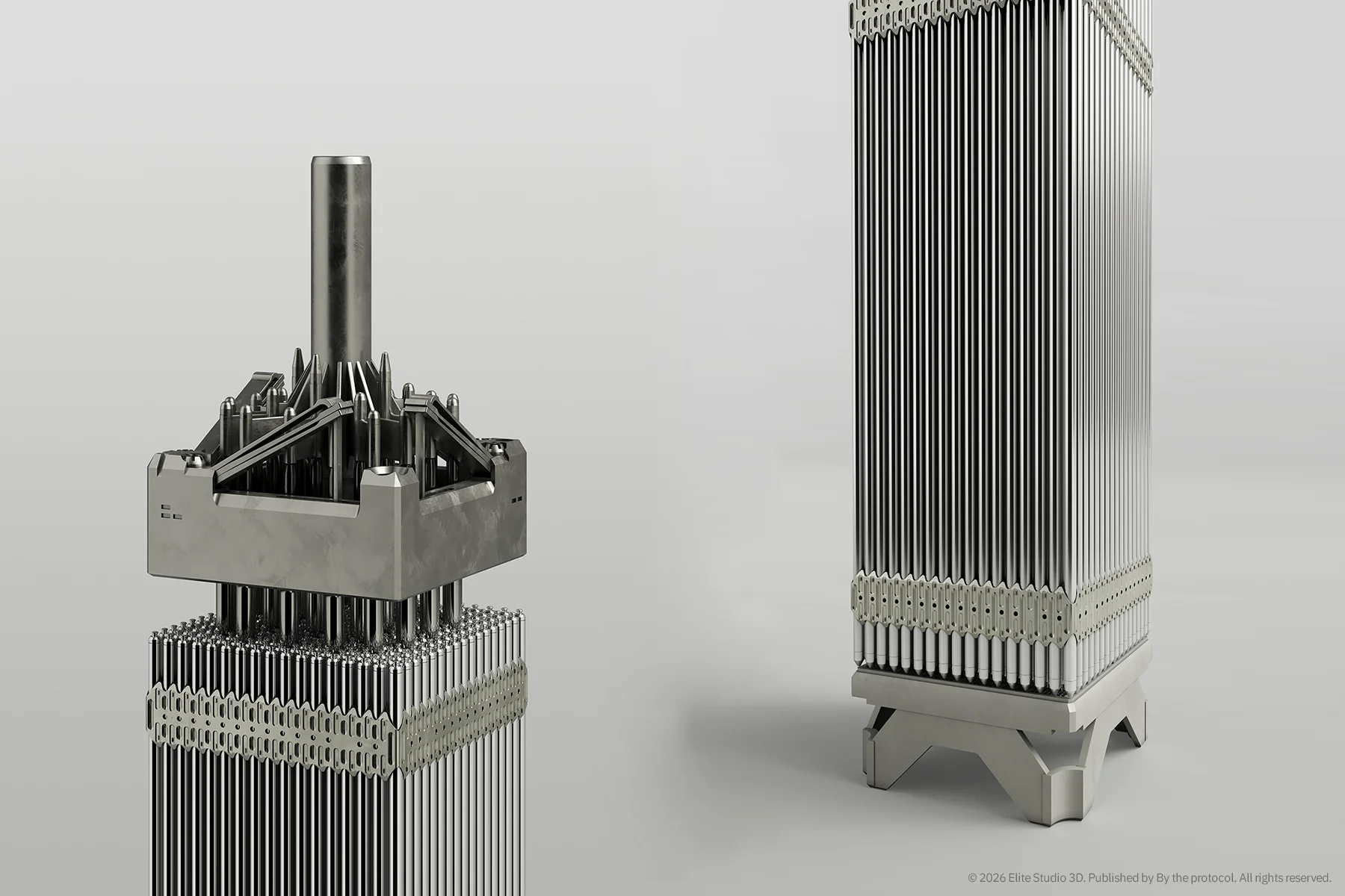

Inside the core: CRA and ICI
Two elements became especially important during the reconstruction: the Control Rod Assemblies, or CRA, and the In-Core Instruments, or ICI. They are easy to overlook in simplified reactor illustrations.
But inside the core, they are not secondary details.
The CRA guide tubes connect to the upper core structure and extend downward into the fuel assembly region. Their role is direct, but non-negotiable: they provide precise and reliable guidance for the control rods that shape reactivity and, when required, shut down the chain reaction.
This is where reactivity control becomes geometry.
A control rod is not only a safety concept in a diagram. It has to move through a defined physical path. It needs alignment, guidance, clearance, and a structure that allows it to reach the correct position when the system requires it.
The ICI positions share the same lattice logic, but they serve a different purpose.
Where an ICI is located, the fuel assembly head is modified. The instrument passes through the square opening in the upper core plate and seats into its dedicated position inside the assembly.
These channels do not control reactivity. They measure. They provide the data that supports core monitoring, analysis, and operational understanding. That distinction matters.
The CRA asks:
How is the reaction controlled?
The ICI asks:
How does the system know what is happening inside the core?
Once both are placed spatially, the core is no longer only a repeated pattern of fuel assemblies. It becomes a controlled and monitored system.

The core as a system of relationships
A reactor core is not a collection of isolated parts. The fuel assemblies define the active region.
The control rod assemblies introduce the logic of reactivity control and shutdown.
The in-core instrumentation connects the physical core to measurement and monitoring.
The support structures define position, stability, and alignment.
The surrounding barrel and reflector region help define the boundary of the core and the way the internal system is held together.
Once these elements are reconstructed together, the core becomes easier to read. You begin to see why alignment matters. You begin to understand why a small spatial error can disturb the logic of the whole model. You begin to notice that a component is never only a component.
It is also an interface.
This is where documentation-driven 3D reconstruction becomes more than visualization. It becomes a way of checking understanding.
Why this is difficult to model
The most difficult part was not creating an interesting reactor image. The difficult part was maintaining relationships.
The fuel assembly pattern had to make sense. The CRA positions had to relate to the upper structure. The ICI positions had to remain believable within the lattice logic. The support plates, core barrel, reflector structures, and internal geometry had to read as parts of the same system.
In a compact reactor architecture, a small modelling mistake does not stay isolated. If one element is slightly wrong, other elements begin to lose their logic. That is why this type of modelling is slow.
Not because the geometry is impossible. Because the relationships matter. And in nuclear systems, relationships are part of the design logic.
Visualization as a tool for understanding
This model is not an official vendor model. It is not a commercial reconstruction of a proprietary design.
It is an independent technical interpretation based on publicly available documentation, developed for learning, spatial reasoning, and nuclear communication.
For me, 3D modelling in this context became three things at once:
- a learning tool,
- a way to test my own understanding,
- and a bridge between technical documentation and spatial intuition.
Once the CRA positions are placed in relation to the fuel assemblies, they stop being labels in a document.
Once the ICI positions are reconstructed spatially, they stop being lines in a diagram.
Once the core barrel, support plates, and reflector region are understood as part of the same internal architecture, the core becomes readable in a different way.
Not simplified. Readable. That distinction matters.
From source to system
A source document is not copied into 3D. It is interpreted. A technical drawing is not treated as decoration. It is treated as evidence. A model is not built to replace documentation. It is built to understand what documentation implies.
This is the central idea behind the reconstruction process. The value is not in making a reactor look impressive. The value is in making system logic visible.
Carefully. Slowly. With respect for what is known, and with equal respect for what is not publicly documented.
What comes next
The core is the foundation.
From here, the reconstruction continues upward and outward: toward upper internals, support structures, vessel architecture, interfaces, and the wider spatial logic of the reactor system.
Each layer adds another level of understanding. And each layer confirms the same principle: in nuclear systems, nothing is random.
Note
This reconstruction is an independent technical interpretation based on publicly available documentation. It is not an official NuScale Power model, vendor drawing, or proprietary representation of the system. It is created for educational, technical communication, and analytical purposes only, and is not intended for design, engineering, or licensing use.
All visual material, 3D reconstruction work, renders, diagrams, and written analysis remain the intellectual property of Elite Studio 3D / By the Protocol unless stated otherwise.
3D Reconstruction By the Protocol Control Rod Assembly Core Monitoring CRA Engineering Visualization FSAR Fuel Assembly ICI In-Core Instrumentation Nuclear Visualization NuScale Public Documentation PWR Reactivity Control reactor core Reactor Internals Small Modular Reactor SMR Source to System technical reconstruction
Last modified: May 31, 2026