
Dry Cask Storage Is Not a Container. It Is a System.
A documentation-driven 3D reconstruction of the HI-STORM 100S dry cask system, focused on confinement, shielding, passive cooling, criticality control and the spatial logic behind spent fuel storage.

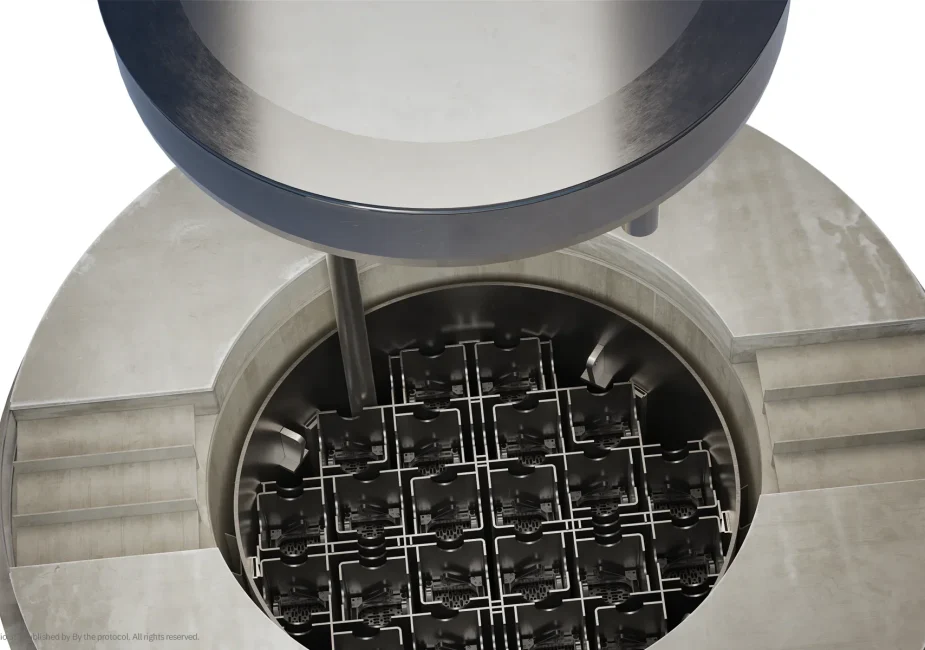
A documentation-driven 3D study of the HI-STORM 100S dry cask system
One of the most persistent public questions about nuclear energy is spent fuel.
Not because the answer is simple, but because the system behind the answer is rarely visible. Spent nuclear fuel remains radioactive and continues to generate heat after it is removed from the reactor. It cannot be treated as ordinary industrial material, and it cannot be explained responsibly through slogans. Its management requires engineered barriers, shielding, heat removal, criticality control, regulation, inspection and long-term procedural discipline.
One of the systems used for this purpose is dry cask storage.
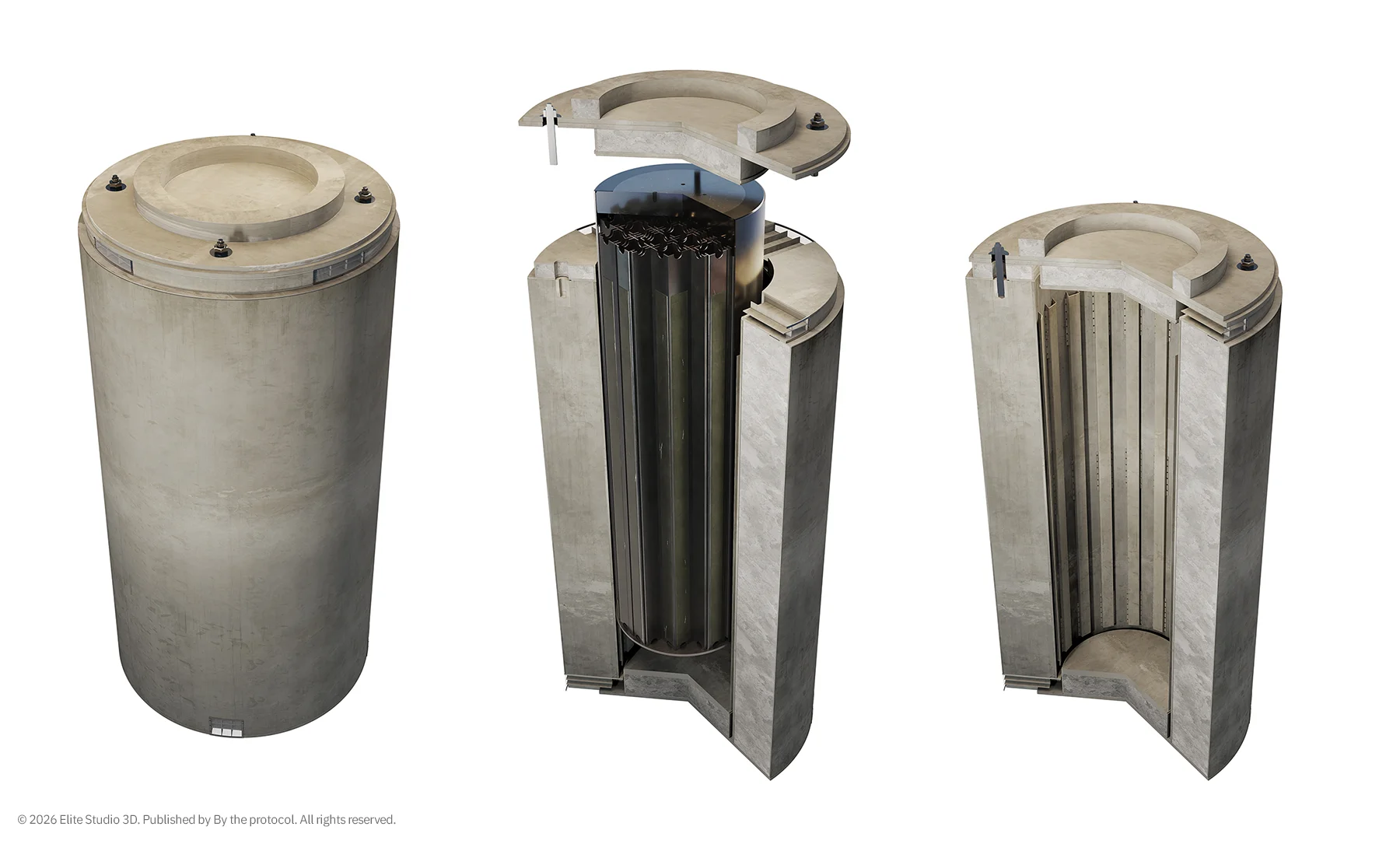
This case study uses a documentation-driven 3D reconstruction of the HI-STORM 100S dry cask system to examine how confinement, shielding, passive cooling and geometry work together.
The purpose of the model was not to create a decorative visualization. It was to understand the system spatially.
- How is the fuel contained?
- Where is the primary barrier?
- How is heat removed without pumps or fans?
- Where does shielding function come from?
- How do internal materials, external mass and air pathways form one controlled safety concept?
The model was developed from technical documentation, including the Final Safety Analysis Report (FSAR), and built from the inside outward. This method allows a system that is normally hidden behind steel and concrete to become readable.
What a Dry Cask Does
Dry cask storage is used after spent nuclear fuel has cooled for several years in a spent fuel pool.
At that stage, the fuel is no longer used in the reactor, but it still produces residual heat and remains radioactive. A storage system therefore has to perform several functions at the same time:
confinement, shielding, passive heat removal and criticality control.
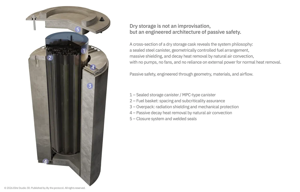
In the HI-STORM 100S system, the spent fuel is placed inside a multi-purpose canister, or MPC. The MPC is a welded steel canister and acts as the primary confinement boundary.
The MPC is then placed inside a massive overpack. The overpack combines steel shells with a thick concrete shielding body. The concrete contributes shielding mass, while neutron absorber materials inside the fuel basket support criticality control.
The system is passive.
There are no pumps, fans or active mechanical components required for normal heat removal. Air enters through lower ventilation openings, flows upward along the heated canister surface, and exits through openings near the top. This natural circulation removes residual heat from the spent fuel without electrical power and without moving parts.
This is where dry cask storage becomes important to understand visually. It is not simply a large concrete cylinder. It is a system of barriers, materials, clearances and air paths.
From Documentation to Geometry
The first step in the reconstruction process was reading the documentation. FSAR drawings often provide sections, dimensions, material references and system descriptions. But these drawings are not always intended to function as complete visual explanations. Some details are simplified. Some relationships are described in text rather than shown clearly in section.
That is where 3D reconstruction becomes useful. A drawing may show the general position of a lid. A table may define the material. A section may show a cavity, a ring or a ventilation path. A note may clarify what the simplified section does not show. The modelling process brings these pieces together into one spatial interpretation.
The goal is not to invent missing detail.
The goal is to respect the available documentation and make the system logic visible.
Fuel Basket and Multi-Purpose Canister
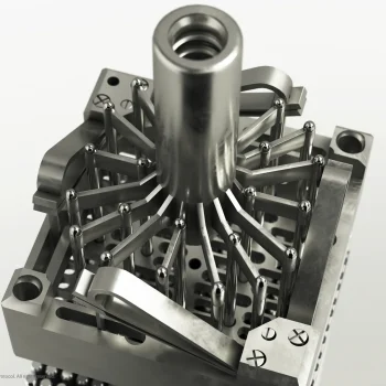
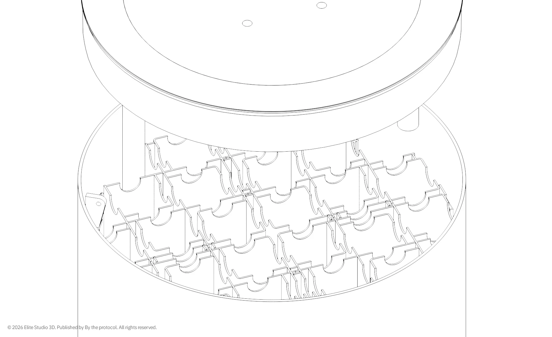
The reconstruction began with the internal structure: the fuel basket inside the multi-purpose canister.
The fuel basket is made from stainless steel and holds the spent fuel assemblies in defined positions. Along the sides of the basket cells are neutron absorber panels, such as Boral or Metamic, depending on configuration. These materials are essential because they absorb neutrons and support criticality control.
In the real system, these absorber plates are not visible from the outside. In the 3D model, they were given a distinct material treatment so their function could be understood by the viewer.
This was a visual decision, but not a decorative one.
It was a communication decision.
The model had to show that safety is not produced by mass alone. It is produced by the relationship between geometry, materials, separation, shielding and neutron behavior.
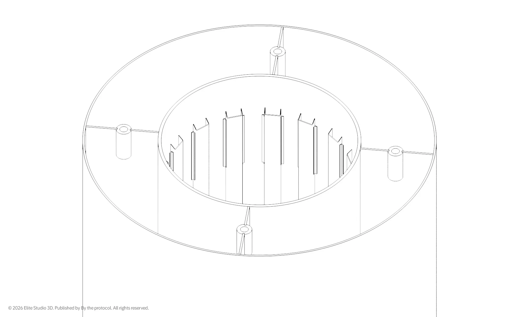
The MPC itself was modelled as a steel cylinder with a welded closure, following its function as the sealed confinement barrier around the spent fuel.
Overpack and Concrete Shielding
After the internal components were defined, the overpack was added.
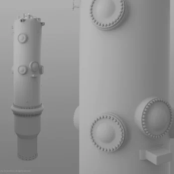
The overpack consists of an inner and outer steel shell with concrete between them. This concrete body is one of the most visually recognizable parts of the system, but its role is not visual. It provides shielding mass and contributes to the overall robustness of the structure. The proportions were important.
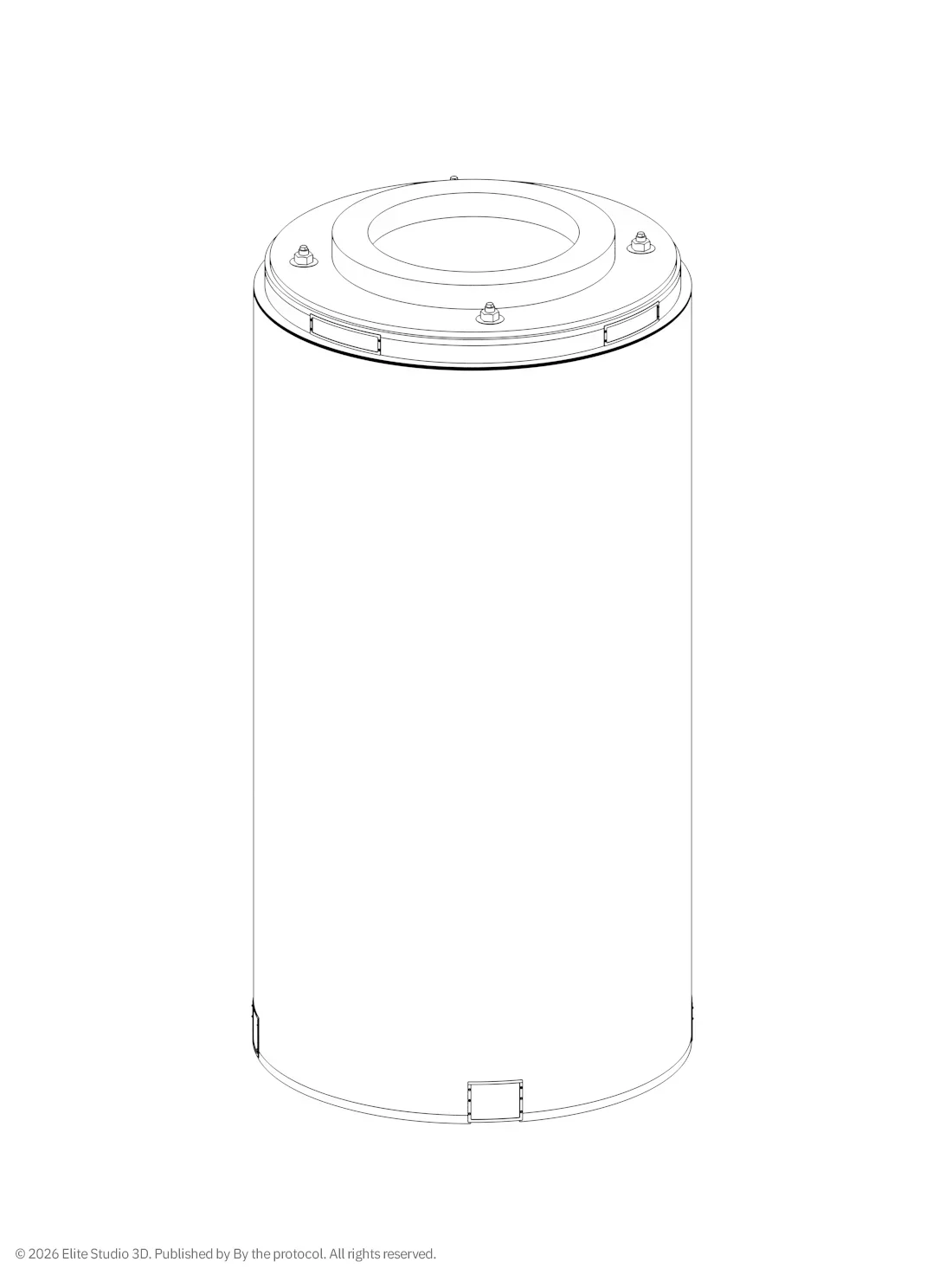
The HI-STORM 100S has a strong and recognizable cylindrical form. Its height, diameter, cavity dimensions and ventilation openings are not arbitrary. They are part of the system’s physical and safety logic.
In the model, the overpack height, diameter and internal MPC cavity were checked against the documented dimensions. This helped keep the reconstruction grounded and prevented it from becoming a generic “nuclear container” visual. The lower and upper ventilation openings were also placed carefully because they are essential to the passive cooling path. Without them, the object may still look like a cask. But it would no longer explain how the system works.
The Top Lid as a Layered Assembly
The most important interpretation work was in the upper part of the cask. In simplified drawings, the top lid can appear almost like a single plate above the concrete. In detailed sections and descriptions, however, the upper closure is more complex. It includes several functional layers and structural elements, including the shield block ring, lid shield, shear ring, heat shield, top plate and anchor studs. For that reason, the lid was not modelled as one simple cover.
It was built as a layered assembly. This matters because the top of the cask is not only a closure. It is part of the shielding concept, the structural concept and the ventilation geometry. The lid also interacts with the upper ventilation region. Air heated by the MPC exits through the upper part of the system, so the relationship between the lid, the steel shell and the ventilation path had to remain readable.
This is a good example of why documentation-driven 3D work is not just modelling.
It is interpretation under constraint.
Material Logic
The model used a restrained material scheme to make the system legible:
| System element | Visual treatment |
|---|---|
| Carbon steel | Dark blue-grey |
| Stainless steel | Cold silver |
| Concrete | Light grey |
| Neutron absorber plates | Visually separated for educational clarity |
| Studs and nuts | Black |
The purpose was not realism alone. The purpose was readability. In technical communication, material separation helps the viewer understand which parts belong to which function. Steel, concrete, absorber material and fuel basket geometry do different things. If they are visually merged, the logic of the system becomes harder to read. A dry cask is visually simple from the outside, but internally it is a layered system.
The model had to make that layered logic visible.
What the Model Shows
From the outside, the HI-STORM 100S appears as a robust cylindrical structure with upper and lower ventilation openings, a massive shielding body and a steel outer shell.
In section view, the system becomes clearer:
- the fuel basket,
- the spent fuel assemblies,
- the neutron absorber plates,
- the welded MPC,
- the concrete shielding body,
- the steel shells,
- the ventilation paths,
- and the layered top lid assembly.
This is where the model becomes useful as a communication tool. It does not simply show what the dry cask looks like. It shows how different safety functions occupy physical space. Confinement is not abstract. It has a boundary. Shielding is not abstract. It has thickness, density and material. Passive cooling is not abstract. It has an inlet, a flow path and an outlet. Criticality control is not abstract. It depends on geometry, absorber materials and separation.
This is the value of spatial reconstruction: it turns technical documentation into a system that can be read.
Why This Matters for Nuclear Communication
Spent fuel storage is often discussed in public as a problem, a fear or a political argument. But before any serious discussion can happen, the system itself has to be understood. A dry cask is not a promise of safety.
It is an engineered arrangement of barriers, materials, passive functions, inspections and regulatory requirements.
Good nuclear communication should not ask people to trust what they cannot see. It should make the logic visible enough that trust can be connected to understanding.
This is the purpose of the reconstruction. Not to simplify the subject until it becomes harmless. But to show that complexity can be explained without making it superficial.
Reflection
The process of modelling the HI-STORM 100S dry cask showed how differently technical documentation behaves once it is translated into space.
A section is not just a drawing. It is a clue about depth, sequence, clearance, material and function. A lid is not just a cover. It is part of shielding, structure, closure and airflow. A concrete body is not just mass. It is part of a radiological protection strategy. A ventilation opening is not just a hole. It is part of passive heat removal.
Each layer exists for a reason.
That is why documentation-driven 3D reconstruction can be valuable in nuclear communication. It does not replace engineering analysis, licensing documentation or official system drawings. But it can help build spatial understanding. And spatial understanding matters.
Because complex systems are often misunderstood when they are only described in
Disclaimer
This reconstruction is an original 3D visualization by Elite Studio 3D, published by By the Protocol.
It was developed for educational, analytical and technical communication purposes using publicly available technical references. It is not an official Holtec International model, drawing or technical representation. It is not plant-specific documentation, operational guidance or licensing material.
All visual material remains the intellectual property of Elite Studio 3D.
© 2026 Elite Studio 3D. Published by By the Protocol. All rights reserved
Documentation-Driven Reconstruction Dry Cask Storage FSAR-Based Reconstruction HI-STORM 100S MPC Passive Cooling Radiation Shielding Spent Fuel Technical Visualization
Last modified: August 21, 2026