

At first glance, a fuel assembly is a repeating lattice of rods, guide tubes and grids. Its orderly exterior can conceal the complexity of the connections between its components. Spacing affects the amount of water between the rods and the coolant flow, support points limit rod movement, and the structural skeleton must maintain the assembly geometry while allowing control rod insertion.
My reconstruction of the NuScale SMR therefore began with a spacer grid, rather than the reactor vessel or the complete core. Only once I understood the grid structure and its interface with the rods did it make sense to proceed towards the complete fuel assembly.
The technical data below refer to the design described in the publicly available NuScale Final Safety Analysis Report (FSAR), Part 2, Tier 2, Chapter 4, Revision 5, dated July 2020. This defines the documentary basis for the explanation. Individual data cannot automatically be applied to all SMR designs.
Starting with the spacer grid
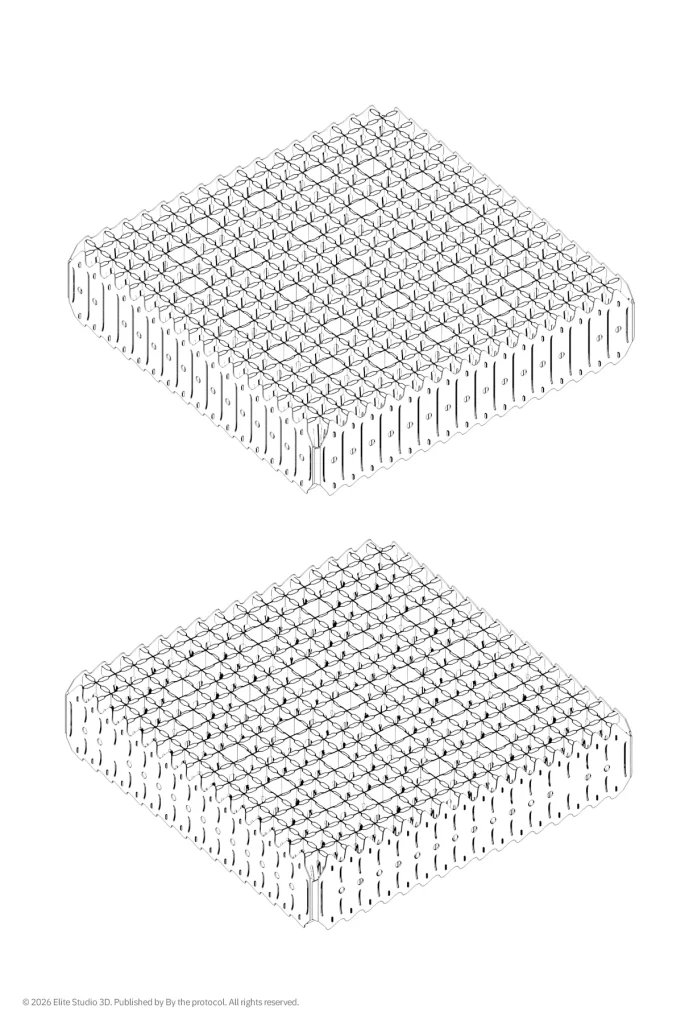
A spacer grid maintains the relative positions of the fuel rods and defines the local flow passages. Contact between a rod and its grid also matters because of vibration and cladding wear at the support points. This wear mechanism is known as grid-to-rod fretting (GTRF). Supporting the rod and directing the coolant are therefore closely related functions.
The names HMP, High Mechanical Performance, and HTP, High Thermal Performance, emphasise characteristics of the respective designs. Both types of grid support the rods, but they differ in their materials and flow-channel geometry. HTP channels are shaped to promote coolant swirl and mixing. HMP uses straight channels and Alloy 718, whose properties help maintain the rod clamping force under irradiation. Understanding this relationship between material, rod contact and flow is more useful than simply expanding the acronyms.
| Grid | Position in the assembly | Material | Flow channels |
| HMP | One bottom grid | Alloy 718 | Straight |
| HTP | Three intermediate grids and one top grid | Zircaloy-4 | Inclined outlets to induce coolant swirl |
Modelling required me to understand the grid as an interconnected structure of formed strips and contact surfaces. Reproducing its outer perimeter in three dimensions was insufficient. I also had to align the cells, guide tube positions and repeating internal elements while keeping the documented geometry distinct from its simplified representation.
What the fuel assembly lattice defines
The designation 17 × 17 describes a lattice of 289 positions. The assembly considered here contains 264 fuel rods, 24 guide tubes and one central instrumentation tube. The guide tubes accommodate the control rods, while the instrumentation tube accommodates measurement equipment. Several different functions are therefore contained within the regular lattice.
The centre-to-centre spacing of adjacent rods, their diameter and the arrangement of the tubes together define the geometry of the flow subchannels and the fuel-to-water ratio. In a pressurised water reactor, water both removes heat and moderates neutrons. A change in geometry can therefore affect reactor physics, flow distribution and local cooling conditions.
Reconstructing the lattice required consistent alignment over the full height of the assembly. A position in one grid must align with the same rod or tube in the next. Checking this alignment reveals offsets and inconsistencies that a single external view may conceal.
Lengths also need to be compared on the same basis. The FSAR specifies an overall fuel assembly length, including the springs, of 95.89 inches, or approximately 2.44 m. The fuel rod is approximately 2.16 m long, while the fuel stack is approximately 2.00 m long. The latter describes the region occupied by fuel pellets and differs from the overall assembly length. These dimensions are listed in Table 4.2-1.
From grids to the structural skeleton
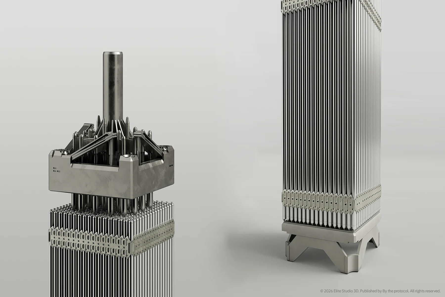
Once the grid structure was understood, the model expanded to include the guide tubes, central instrumentation tube, fuel rods, and top and bottom nozzles. At this stage, I needed to follow the connections between the components. The grids define the rod support locations, while the guide tubes and nozzles connect the components into a structural skeleton.
In Framatome’s HTP design, the intermediate grids are welded to the guide tubes, while the bottom HMP grid is retained by rings welded to the guide tubes. These connections help maintain the relative positions of the components during fuel handling and operation. The 3D representation must therefore also make clear how each grid is attached or retained.
The bottom nozzle transfers loads to the core support structure and defines the coolant inlet to the assembly. It includes a filter plate to retain debris that could damage the fuel rods. The public NuScale presentation identifies this component as a coarse-mesh filter plate. The frame is made of stainless steel and the filter plate of Alloy A-286. Coarse-mesh filter is therefore the term used here for the documented bottom-nozzle design.
The top nozzle interfaces with the upper reactor internals. Flow openings allow the coolant to leave the assembly, while spring elements help hold the assembly in its intended position. Explaining its function therefore requires attention to the mechanical interface, coolant flow and clearance for control rod movement.
The control rod assembly (CRA) is a separate moving component. Its rods are connected to a common support and are inserted into the fuel assembly guide tubes. In a view from above, it is therefore useful to distinguish the top nozzle, its springs and the control rod support. An exploded view makes the individual connections easier to see, but the positions shown do not represent the operating configuration.
The coolant path through the fuel assembly
The main coolant flow enters through the bottom nozzle and rises through the spaces between the fuel rods. It receives heat through the rod cladding, then passes through the top nozzle into the region above the core. Along this path, the grids alter the local flow direction and distribution and contribute to hydraulic resistance.
Coolant mixing can improve local heat transfer, but its benefit must be considered alongside the pressure drop across the assembly. A reconstruction should therefore show how the bottom-nozzle flow openings, subchannels between the rods and passages through the grids form a continuous flow path. Geometry alone does not establish the pressure drop or thermal margins.
During normal operation, NuScale uses natural circulation of the primary coolant. The driving head results from density differences between the hotter and colder sections of the circulation path and their vertical distribution. The available driving head must overcome the resistance of the entire circuit, so the contributions of the fuel assembly, reactor internals and steam generators also matter. The shorter fuel assembly needs to be understood within this complete flow path.
Comparison with a large PWR fuel assembly
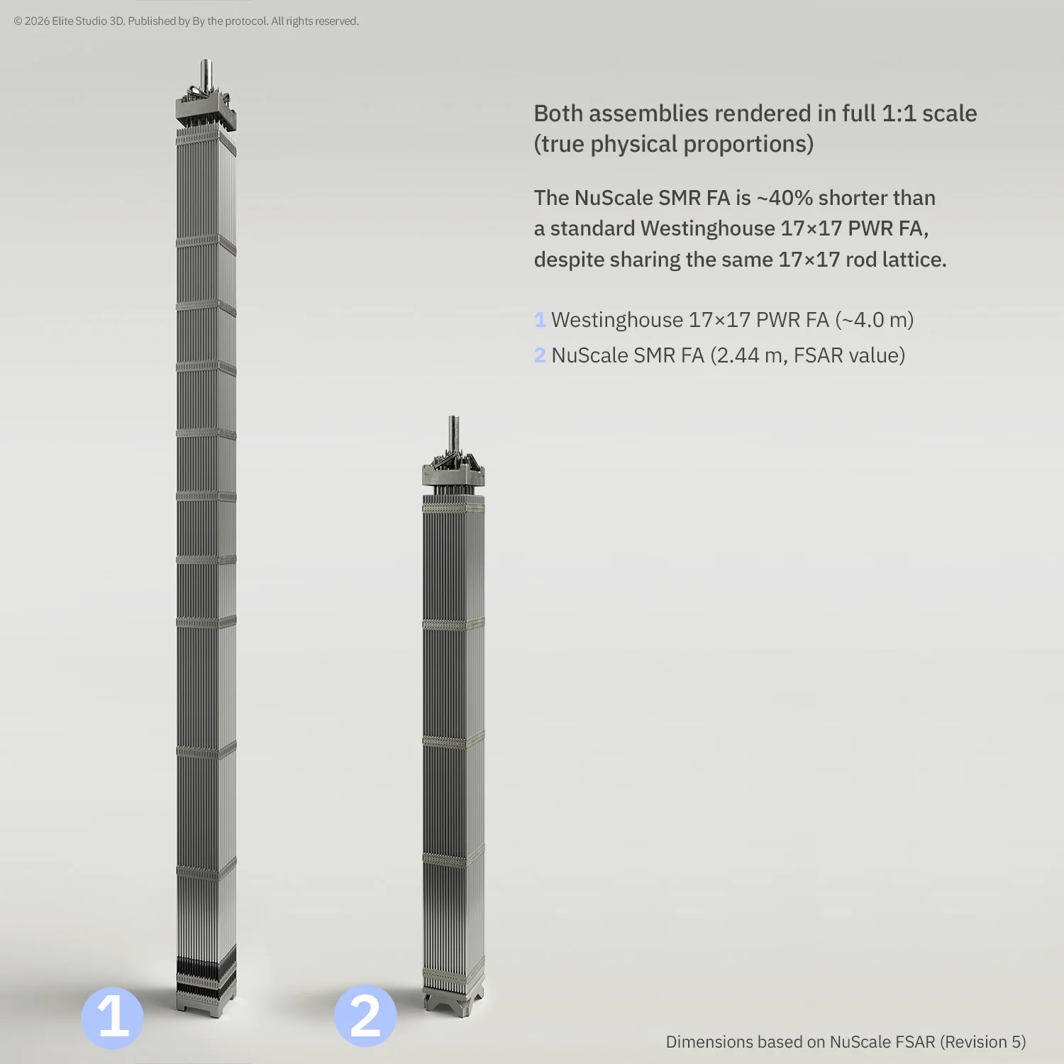
The next step was a comparison with a Westinghouse 17 × 17 reference fuel assembly for a large pressurised water reactor (PWR). In my comparison model, that assembly is approximately 4.0 m long, whereas the NuScale assembly considered here measures approximately 2.44 m. The Westinghouse value refers to the selected reference model. The designation 17 × 17 alone does not specify a uniform length for all fuel assemblies.
A shorter structure changes the distances between components and the conditions under which the assembly must maintain alignment. Assessing the effects on stiffness, vibration and flow also requires information on materials, connections, support locations and loads. These properties cannot be calculated from a visual comparison of heights.
The comparison also involves different suppliers’ designs. NuScale uses fuel developed from established Framatome 17 × 17 technology. Differences in grid geometry, nozzle design and component connections therefore do not necessarily result from the distinction between a large reactor and an SMR. Some arise from the particular fuel design family.
The difference at system level remains significant. In a conventional large PWR, reactor coolant pumps maintain primary flow between the core and the external steam generators. The NuScale design considered here is an integral PWR using natural circulation. In both cases, the fuel assembly must be assessed in relation to the flow, thermal loading and support geometry of the reactor for which it was developed.
Modelling as technical interpretation
At this stage, the model was used to check the spatial consistency of the documented components. It helped me trace the fuel rod axes through successive grids, connect the guide tubes to the nozzles and examine the coolant passages. This representation allows information from different views and descriptions to be considered together.
Geometric checking must be distinguished from demonstrating performance in operation. A reconstruction can show the component arrangement and intended load paths. Determining stresses, vibration response, pressure drop or thermal-hydraulic margins requires appropriate analytical models and tests. These are outside the scope of this reconstruction for technical study.
The main contribution of the work was to bring the documentation together. I came to understand the spacer grid through its contact with the rod, then through its connection to the guide tube, and finally through its position within the complete assembly. This progressively clarified which geometric features had to be preserved for the model to remain useful in explaining how the system works.
Documentation discipline
The model is an independent reconstruction for technical study, based on publicly available FSAR documentation and suppliers’ technical publications. No proprietary or confidential CAD data were used. Where public sources provide dimensions, the geometry follows those data. Details without an adequate documentary basis are simplified.
The visualisation is intended for education and technical communication. It is not an official NuScale Power or Framatome model, manufacturing documentation, or a demonstration of the mechanical or thermal-hydraulic adequacy of commercial fuel. The accuracy of each part of the representation is limited by the scope and quality of the public sources.
The completed assembly emerged through successive reading, comparison and reconciliation of the geometry. Starting with the grid proved useful because, even at that level, material properties, rod support and coolant flow had to be considered together. The complete model then made these relationships visible beyond any individual drawing.
Note on illustrations
The cover visualisation and the illustrations of the spacer grids and the upper and lower portions of the fuel assembly are original work by Elite Studio 3D / By the Protocol. They are based on an independent interpretation of public technical documentation. Exploded views are used to explain connections between components. Colours and surface appearances serve the visual presentation and do not establish the actual surface finish or material condition.
References and documentary basis
NuScale Power, LLC. NuScale Standard Plant Design Certification Application. Part 2, Tier 2, Chapter 4, Reactor. Revision 5, July 2020. For the fuel assembly description: Section 4.2.2, Tables 4.2-1 and 4.2-2, and Figures 4.2-1 to 4.2-10. For the flow and cooling context: Section 4.4.
NuScale US600 application documents on the NRC website
NuScale Power, LLC. ACRS Presentation: NuScale Chapter 4, Reactor Overview. PM-0419-65096, Revision 0, 17 April 2019. In particular, slides 5 to 7 on the grids and bottom nozzle, and slide 15 on the origins of the fuel design. NRC ADAMS: ML19105A131.
Publicly available text of the presentation
Framatome. HTP: Robust Technology for PWR Fuel Assemblies. PS_US_328_ENG_05_18, 2018. Description of the common features of HTP and HMP technology and the structural skeleton connections. Optional features described in this general publication are not necessarily part of the NuScale fuel assembly considered here.
Framatome HTP and the associated technical sheet
17x17 Engineering Visualization Framatome FSAR Fuel Assembly HMP HTP NuScale PWR SMR spacer grids technical reconstruction Westinghouse
Last modified: October 12, 2026